SCEA065B November 2018 – March 2021 SN74AVC4T774 , SN74AXC1T45 , SN74AXC4T245 , SN74AXC4T774 , SN74AXC8T245 , SN74AXC8T245-Q1 , SN74AXCH1T45 , SN74AXCH4T245 , SN74AXCH8T245
2.3.1 Voltage Translation With UART
To use UART between two devices operating at different voltage levels, a voltage translator is necessary. Depending on the system configuration, either SN74AXC1T45 or SN74AXC4T245 voltage translators may be used.
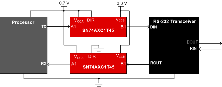
For a simple two line interface, two SN74AXC1T45 on each data line can be implemented to achieve voltage translation. This configuration requires the direction pin on one device to be pulled to VCCA high to achieve A to B translation, and the DIR pin of the other device pulled to ground to achieve B to A translation as shown in Figure 2-5.
For the four line interface, SN74AXC4T245 can be used with DIR1 pin pulled to VCCA and the other DIR2 pin pulled to ground. This ensures that two channels translate from A to B and two channels translate B to A. The TX and CTS lines should communicate in one direction, while RX and RTS communicate in the opposite direction as shown in Figure 2-6.
 Figure 2-6 4-wire UART Voltage
Translation Using SN74AXC4T245
Figure 2-6 4-wire UART Voltage
Translation Using SN74AXC4T245Another common UART configuration is having two separate UARTs running. To achieve translation in this configuration, the SN74AXC4T245 can be used. The setup is the same as the 4-line UART, with both direction pins being pulled to VCCA. In this configuration, both TX lines would run in the same direction, opposite to the two RX lines as shown in Figure 2-7.
 Figure 2-7 Two 2-wire UART Interface
Voltage Translation Using SN74AXC4T245
Figure 2-7 Two 2-wire UART Interface
Voltage Translation Using SN74AXC4T245