SLOA292 May 2020 TAS5760LD
5.1 Terminations Resistor Design With Practical Application Waveform
On a real application, the output transient is improved from -11 mV to -2 mV as shown in Figure 13 by decreasing termination resistor from 1 kΩ to 270 Ω resistor.
Pros: Termination resistor decrease the output transient obviously.
Cons: The current is higher if using smaller termination resistor. From Equation 2, the power consumption increases 3.7 times if using 270 Ω resistor.
Equation 2. 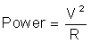
Equation 3. 
 Figure 13. TAS5760LD Line Driver’s Waveform With 270 Ω Termination Resistor
 CH1 is input from SOC. CH2 is line driver output. CH3 is (DR_MUTE ) controlled waveform by SOC’s GPIO. CH4 is 3.3V for line driver power. The output transient is improved from -11mV.