SLVAE49C April 2019 – April 2022 DRV8847 , DRV8873-Q1 , DRV8904-Q1 , DRV8906-Q1 , DRV8908-Q1 , DRV8910-Q1 , DRV8912-Q1
5 Negative-Current Active Open Load Detection
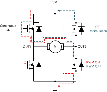
In negative-current active OLD, found in the DRV89xx-Q1 devices, the current OLD threshold is negative (IOLD_NEG). The negative current re-circulation occurs through the current re-circulation FET in synchronous rectification. Figure 5-1 shows the operation of the H-bridge when forward driving and when using synchronous rectification. If negative-current active OLD is not utilized, the device can show a false OLD since the current re-circulating through the current re-circulation FET is negative and it is less than the positive current OLD threshold the other active OLD diagnostics use. When the negative-current active OLD is enabled, this negative flow of current through the current re-circulation FET does not show false OLD event due now utilizing a negative-current active OLD current setting (IOLD_NEG).
 Figure 5-1 Forward Drive and Braking in
Synchronous Rectification
Figure 5-1 Forward Drive and Braking in
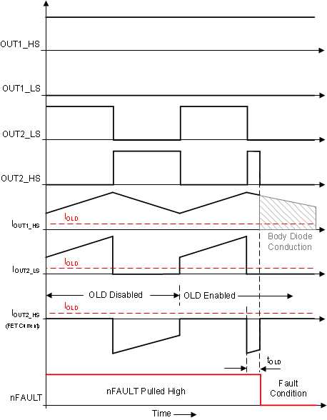
Synchronous RectificationFigure 5-2 shows the waveforms of false OLD when the negative-current active OLD is not active in an H-bridge configuration. In synchronous rectification with high-side current re-circulation, one of the driving FETs is always turned ON and the other driven half-bridge's low-side and high-side FETs operate in a complimentary manner. Initially, for the first PWM cycle, all OLD diagnostics are disabled to show the currents in the different FETs during the load operation. If the active OLD diagnostic is enabled in the second PWM cycle, then the device registers a false OLD flag during the high-side FET current re-circulation due to the negative current. This false flag will cause both of the switching high-side and low-side FETs to be turned OFF. Since the fault causes OUT2_HS to turn OFF, the high-side FET's body diode instead of the high-side FET conducts to complete the current re-circulation path back to the supply.
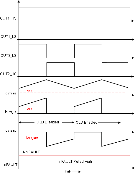
This false OLD flag is eliminated by enabling the negative-current OLD. Figure 5-3 the negative-current active OLD current setting (IOLD_NEG) is enabled for the current re-circulation FET of the switching half-bridge. Since the current threshold is negative and greater than the current re-circulating through the current re-circulation FET, the false OLD flag is prevented and the FETs of the switching half-bridge are not disabled in the second PWM cycle. With setting the current threshold to a negative value, the OLD flags where the load is disconnected during synchronous rectification can be detected. There is no tradeoff to enabling the negative-current active OLD.
 Figure 5-2 False OLD Flag with
Negative-Current OLD Disabled
 Figure 5-3 No False OLD Flag with
Negative-Current OLD Enabled