SLVAE49C April 2019 – April 2022 DRV8847 , DRV8873-Q1 , DRV8904-Q1 , DRV8906-Q1 , DRV8908-Q1 , DRV8910-Q1 , DRV8912-Q1
1.3 Load Connected to H-Bridge
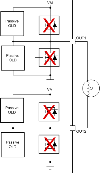
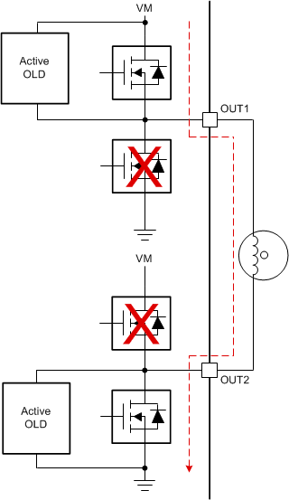
In this configuration, the bidirectional motor or solenoid / relay load is connected between two outputs (for example OUT1 and OUT2) as shown in Figure 1-5 (Passive OLD) and Figure 1-6 (Active OLD). This configuration is widely used for bidirectional control of loads. This configuration gives flexibility to change the direction of the load by opposing the voltage polarity at OUT1 and OUT2. During the passive OLD, there is no current flow to the load. During active OLD, the load's current flows VM to either OUT1 or OUT2, then to the other output and finally to GND when a half-bridge’s high-side FET and the other driven half-bridge’s low-side FET are turned ON. To drive in the opposite polarity, those FETs are turned OFF and the FETs that were OFF are now turned ON.
 Figure 1-5 Passive OLD for Load
Connected in H-Bridge Configuration
 Figure 1-6 Active OLD for Load
Connected in H-Bridge Configuration