SLVUBO3A April 2019 – October 2020 TPS650330-Q1
- Trademarks
- 1BOOSTXL-TPS65033 Components and Environment
- 2BOOSTXL-TPS65033 Board Information
- 3Programming GUI Operation
- 4Recommended Operating Procedure
- 5BOOSTXL-TPS65033 Schematic
- 6BOOSTXL-TPS65033 Board Layers
- 7BOOSTXL-TPS65033 Bill of Materials
- 8Revision History
3.1.4 Flashing the MSP432E401Y Launch Pad
Initial operation with the MSP432E401Y LaunchPad requires downloading pre-configured firmware into the MSP432 in order to be recognized by the GUI. See Section 3.1.2 about how this firmware must be accessed by installing the GUI for offline operation.
- Once downloaded, the MSP432 firmware file, acctrl_4_18.bin, can be found at:{Installation Directory}\install_image_TPS6503xx-Q1_GUI.zip\TPS6503xx-Q1_GUI\app\firmware
- Install UniFlash, a free firmware flashing tool from TI.
- Connect the LaunchPad to the PC. Use the USB port on the MSP432E401Y LaunchPad that is opposite the Ethernet port.
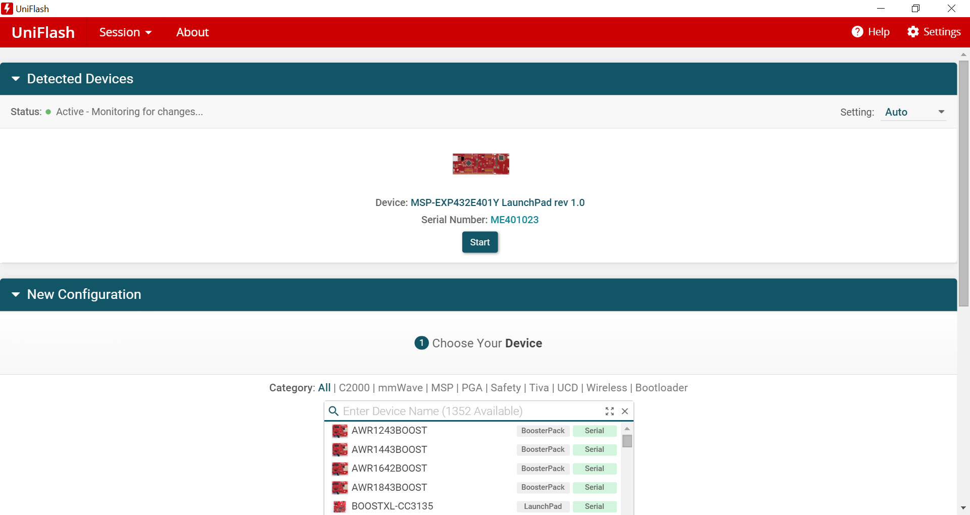
- Run UniFlash. The program should
automatically detect the connected MSP432E401Y LaunchPad. Once detected, click
Start.
 Figure 3-4 UniFlash Initial
Setup
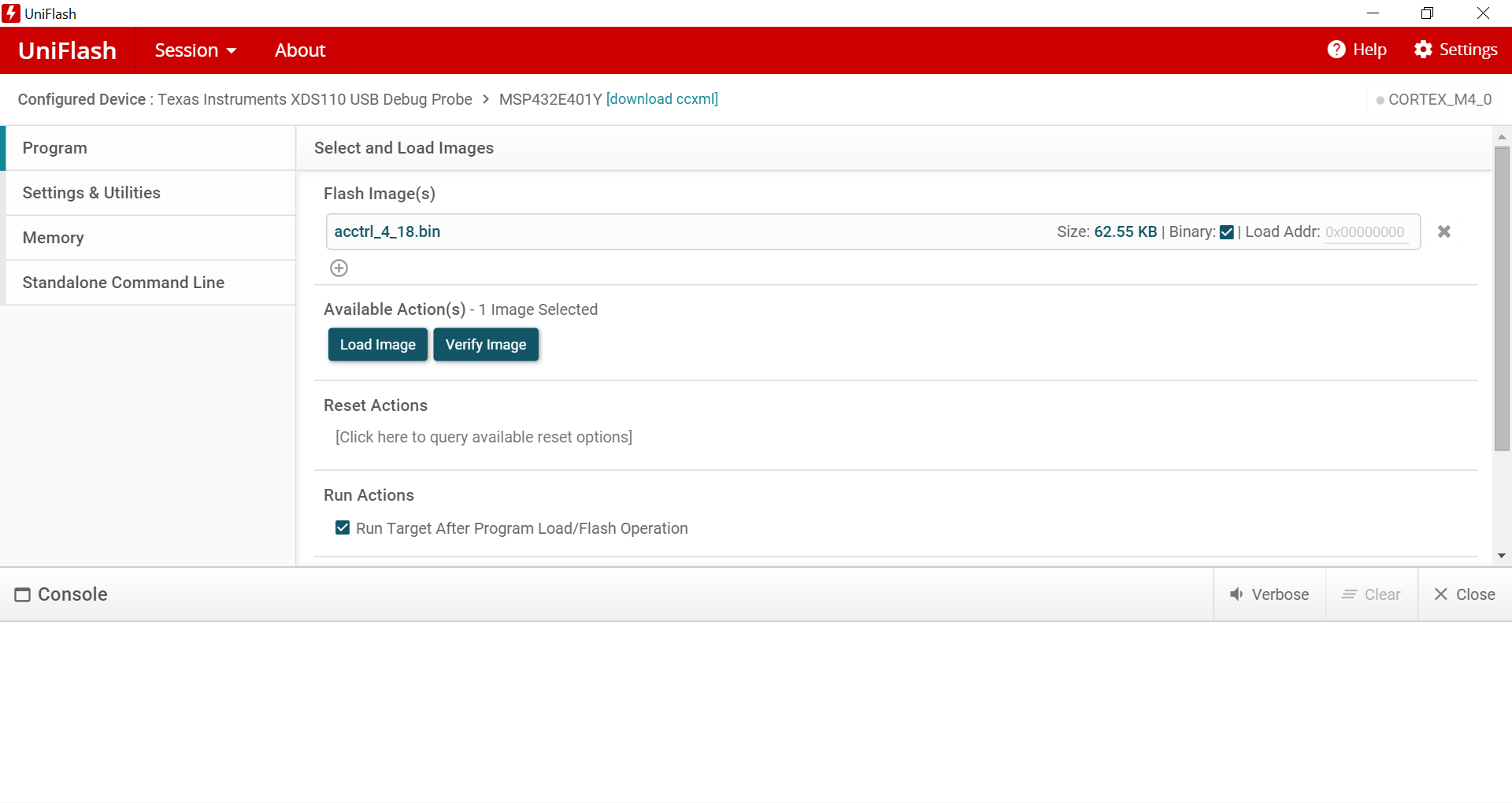
 - On the next page, browse to the
binary file downloaded in Step 1 and click Load Image.
 Figure 3-5 UniFlash Load Firmware
Image
 - If prompted, update the XDS110
Debugger firmware. After accepting the update, UniFlash will update the firmware
automatically and continue to load the binary image. The console will indicate a
successful program.
 Figure 3-6 UniFlash Successful
Program
 - Unplug the micro USB cable from the MSP432E401Y LaunchPad.
- Now plug the USB cable in to the micro USB port adjacent to the Ethernet port.
- Install jumper on pins 3-4 (USB-OTG) of JP1 to supply the target 5 V supply through USB.
After completing this process, the GUI will recognize the LaunchPad as a USB-to-I2C interface. Next, stack the BOOSTXL-TPS65033 on top of the MSP432E401Y LaunchPad. The headers should align according to Table 3-1.
| BOOSTXL-TPS65033 Pin Header | MSP432E401Y LaunchPad Pin Header |
| J1 | J5 |
| J2 | J6 |
| J3 | J7 |
| J4 | J8 |
Note there may be two separate interfaces (or COM ports) recognized by the GUI. If one is failing to connect, use the GUI to switch to an alternate port.
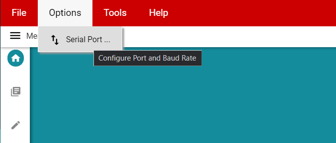
- Click the Options menu at the top
of the GUI, select Serial Port.
 Figure 3-7 Serial Port
Options
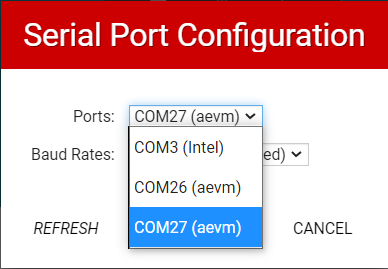
 - Use the Ports dropdown to select
the alternative interface.
 Figure 3-8 GUI Serial Port
Selection
 - The GUI will indicate a successful connection through the black connection toolbar.
 Figure 3-9 Hardware Connected
Indicator