SLWU067D November 2009 – March 2022 ADS4122 , ADS4125 , ADS4126 , ADS4128 , ADS4129 , ADS4142 , ADS4145 , ADS4146 , ADS4149 , ADS41B25 , ADS41B29 , ADS41B49 , ADS58B18 , ADS58B19
4 Quick Start Setup
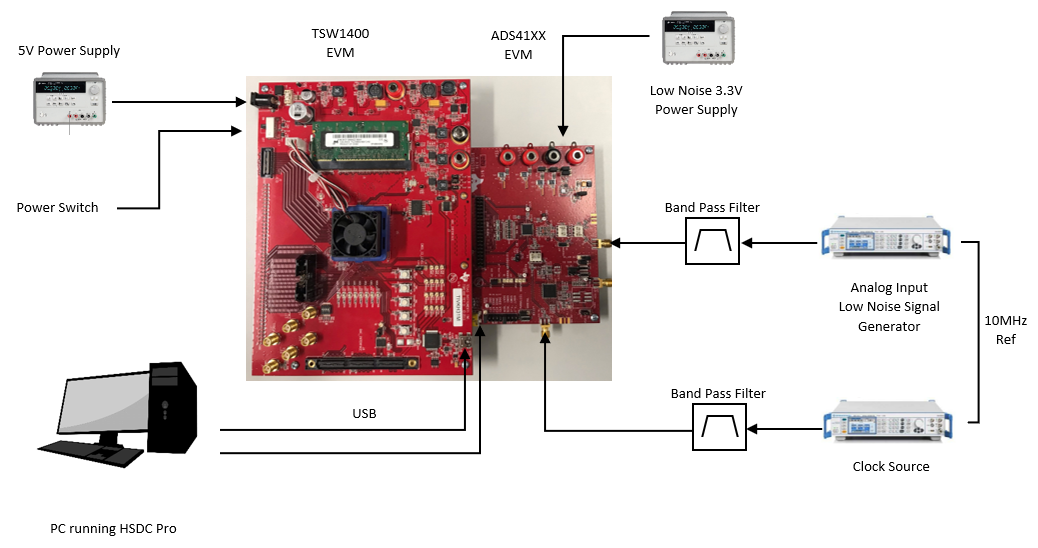
- Set up the ADS41xxEVM according the following diagram.
- Two signal generators are used and externally locked through the 10-MHz reference. Furthermore, bandpass filters on clock and data input are used to minimize spurs and noise created by the signal generators. Depending on filter attenuation, the clock generator amplitude must be set to 10-13 dBm.
- USB connection of the PC to ADS41xxEVM as well as TSW1400 must be established and if necessary the USB drivers installed accordingly (see Section 3.2).
- The ADS41xx EVM requires a 3.3V power supply and the TSW1400 a 5V supply.
- If Serial mode (SPI) is used, ensure that jumpers are set for SPI mode (SCLK, SDATA, SEN).
- Configure the following SPI registers:
- Reset USB.
- Reset ADC.
- Disable low latency mode (ADS41xx only).
- Enable gain (ADS41xx only).
- Set gain to 1 dB (ADS41xx only).
- Configure the TSW1400 (see Figure 5-1).
- In HSDC Pro, under the ‘Select ADC’ drop down, select the ADC under test.
- Under Test Selection, select Single Tone to run a single tone FFT test.
- Change the ADC Output Data Rate and ADC Input Target Frequency to match those of the signal generator.
- Press the Capture button to begin capturing data
- Adjust input signal amplitude until fundamental amplitude reaches ~ –1 dBFS.
- Measurement is illustrated in Figure 5-2.