SLYY109B February 2021 – March 2022 HD3SS3212 , HD3SS460 , TPD4S311A , TPD6S300A , TPD8S300 , TPS25740A , TPS25750 , TPS65982 , TPS65983B , TPS65987D , TPS65988 , TPS65994AD , TUSB1042I , TUSB1046A-DCI , TUSB1210 , TUSB1310A , TUSB320 , TUSB542 , TUSB544 , TUSB546A-DCI , TUSB564
- At a glance
- Authors
- 3
- Introduction
- Data and power roles
- USB Type-C UFP sink: USB 2.0 without USB PD
- USB Type-C DFP: USB 2.0 without USB PD
- USB Type-C DRP/DRD USB 2.0 without USB PD
- USB Type-C DRP/DRD: USB 2.0 with USB PD
- USB 3.1 Gen 1 (SuperSpeed) and Gen 2 (SuperSpeed+)
- Alternate Mode
- USB Type-C pinout and reversibility
- Conclusion
- References
USB Type-C pinout and reversibility
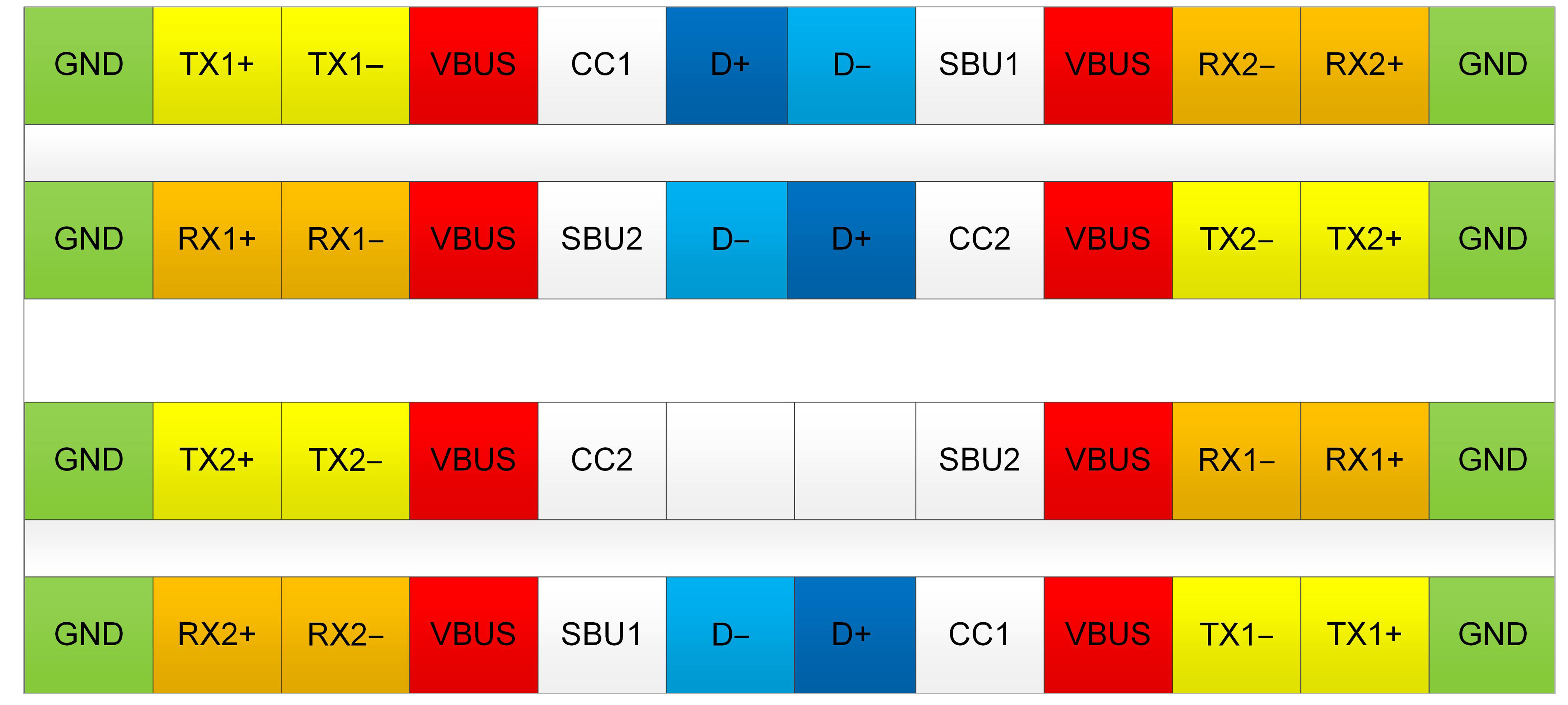
The USB Type-C connector includes several new pins compared to USB Type-A and Type-B connectors. These pins enable USB Type-C features such as higher power, Alternate Mode and reversibility. Figure 13 illustrates the pinout.
From left to right, Figure 13 shows:
- GND: the return path for the signal.
- TX/RX: SuperSpeed twisted pairs for USB 3.1 data (5 to 10 Gbps).
- VBUS: the main system bus (5 V to 20V).
- CC1/CC2: CC lines used for cable detection, orientation and current advertisement. With USB PD, the CC lines can also communicate higher power levels and Alternate Mode. Note that one of the CC lines may become VCONN.
 Figure 13 Type-C receptacle
pinout.
Figure 13 Type-C receptacle
pinout.- SBU1/SBU2: these are low-speed lines used only for Alternate Mode and accessory mode. For example, with DisplayPort, AUX+/AUX– transmit over the SBU lines. For audio adapter accessory mode, these lines are used for the microphone input and analog GND.
- D+/D–: a high-speed twisted pair for USB 2.0 data (up to 480 Mbps).
A new aspect of the USB Type-C connector is that the pins are almost symmetrical (both vertically and horizontally). This is why the connector can be reversible. Unfortunately, it’s not possible to passively realize reversibility, so additional electronics are required. Figure 14 shows how a USB Type-C receptacle (top) and a USB Type-C plug (bottom) are essentially flipped relative to each other.
 Figure 14 Type-C pinout – receptacle
(top), plug (bottom).
Figure 14 Type-C pinout – receptacle
(top), plug (bottom).- The GND and VBUS lines are still in the same position.
- The D+/D– pair is in the same orientation; however, the plug contains only one D+/D– twisted pair. The USB Type-C specification allows shorting of the D+/D– lines together (D+ to D+ and D– to D–) on the receptacle side. Regardless of cable orientation, the PHY will always see the cable’s D+/D– pair.
- The CC1 and CC2 lines are flipped and can determine the cable orientation. The orientation determines which CC line is connected and which one is left open.
- The TX/RX pairs are also flipped.
Resolving this was a bit more complicated. Unlike the D+/D– lines, you cannot
simply short the common lines together, because that will create a stub. At USB
2.0 speeds, a stub is acceptable, but at USB 3.1 speeds, a stub degrades signal
integrity too much. To avoid this, there are two options:
- Use two PHYs and cable-orientation detection to know which PHY to use.
- Have a single PHY and a SuperSpeed mux that switches the correct SuperSpeed lines to the PHY (given the known orientation). This is typically the more economical solution.
- The SBU lines are also flipped; however, this is typically handled within the Alternate Mode PHY (remember that these are slow-speed lines).