SNAU265C june 2021 – july 2023 HDC3020 , HDC3020-Q1 , HDC3021 , HDC3021-Q1 , HDC3022 , HDC3022-Q1
3.5 Offset Error Correction
The Offset Error Correction Algorithm calibrates the device and corrects any observed sensor drift that may be encountered due to device mishandling or exposure to contaminants. There are cases where the devices have been permanently shifted as a result of accelerated aging test exposure, chemical exposure, or device mishandling. Heating the humidity sensor to a high temperature for a long period of time (to bake it) can remove the drift from prolonged exposure to extreme conditions and/or harsh contaminants, but this is not practical after the sensor is in the field for many applications. Devices that exhibit this shift can be expensive to replace and would also consume a lot of time for technicians to replace the system module. Many polymer-based sensors are susceptible to these shifts and finding a solution to correct this kind of error is greatly desired. This algorithm can reduce cost and potentially improve the life of your product.
This section will cover the electrical, mechanical design and the recommended layout required to correct the humidity offset that is observed on the HDC3020. The offset error correction algorithm calibrates the device and corrects any observed sensor drift that may be encountered due to device mishandling or exposure to contaminants.
This feature should be operated using the Trigger-on Demand mode. When the algorithm is done running, the user can continue to run the device in any other mode of their choosing. This feature can work well for devices that exhibits a positive humidity shift.
This technique uses the built-in heater to eliminate the drift. The triggering of the firmware routine could be accomplished any number of ways, from a cloud-connected handset application, button press, triggered periodically, or just on a power-on reset (POR). The exact method implemented is at the discretion of the developer and also based on the application. In the below examples, a software interrupt was used to trigger the execution of the calibration routine. The algorithm can be run as many times as the users would prefer. However, TI recommends to run the algorithm once a year or whenever it is suspected that the device was contaminated by some chemical.
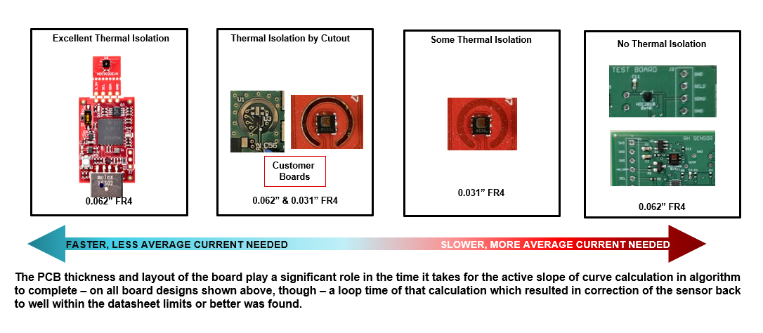
The unit(s) under testing must have their heater switched on and observed for highest temperature that can be achieved. In this effort, the different packages and layouts each have their own impact on the heater performance. Figure 3-4 describes the different layout considerations that can be implemented on the HDC devices. The EVM and the layout with the cutout would require lower current to execute the offset error correction algorithm. However, the layout that has little to no thermal isolation would require a lot more current to execute this command. The device has a recommended 125°C maximum temperature, but certain layouts cannot support this temperature rise. The first step is to see how hot the parts can get on a given layout (if not starting with a cutout), and then change the layout (if possible) to get best results.
 Figure 3-4 Thermal Isolation Examples.
 The HDC3020s heater power setting is also customizable. Users can choose their power setting based on their operating voltage, layout, and overall application, and this can help users reduce their power consumption. Table 3-2 shows some common power settings that were tested along with their approximated power consumptions. If a user plans to modify the heater configuration, a thorough power analysis must be generated along with a look up table.
| HEATER POWER SETTING | HEATER HEX CODE | CRC | TYPICAL HEATER RESISTANCE (Ω) | TYPICAL CURRENT AT 3.3VDC (A) | TYPICALPOWER AT 3.3VDC (W) | TYPICALCURRENT AT 5VDC (A) | TYPICALPOWER AT 5VDC (W) |
|---|---|---|---|---|---|---|---|
25% | 0x009F | 0x96 | 150.35 | 21.95 mA | 72.43 mW | 33.26 mA | 166.29 mW |
50% | 0x03FF | 0x00 | 71.04911037 | 46.45 mA | 153.27 mW | 70.38 mA | 351.87 mW |
100% | 0x3FFF | 0x06 | 35.92 | 91.89 mA | 303.22 mW | 139.22 mA | 696.1 mW |
A characterization table or a look up table (LUT) should be used to apply the correct humidity offset for these devices. TI provides a LUT for two suggested layouts, and one of the recommended layouts can be found in the data sheet. The other suggested layout can be found at the end of this section. The tables were characterized using a Temperature and Humidity chamber (ex: TE1007H) and a high-accuracy temperature and humidity reference (ex: chilled mirror), and the test records the temperature rise from initial conditions until the device reaches the humidity offset. Table 3-2 in the next section records the values between 10% to 45%RH and between 15°C and 30°C.
Figure 3-5 describes the steps required to use the LUT. The humidity value obtained after running this algorithm is the offset that must be subtracted from the device to correct the error. You can apply this offset to the device using the offset register. Refer to the data sheet for more information.
 Figure 3-5 Flowchart Demonstrating the Offset Error Correction Algorithm.
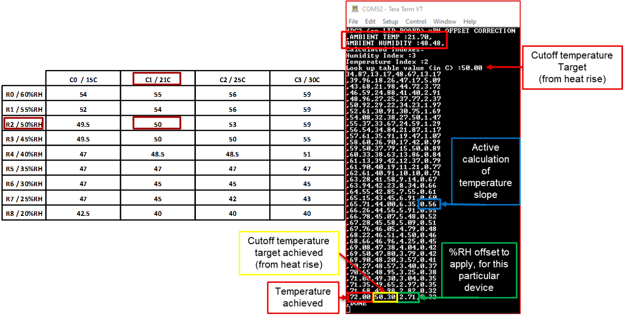
 The algorithm can be executed at any time from normal operation, and successive approximation occurs each time you run it. When the offset is large, running drift correction more than once can help it reach a lower error. The look up table is initialized at the start of the firmware execution. After a read of the ambient conditions, the logic is used to pick out the row and column location value to use for heat rise cutoff temperature. Figure 3-6 shows a quick example of how the overall rise temperature can be selected from a LUT and what value should be subtracted from the offset register. In Figure 3-6, Rx (the first column) represents the humidity %RH set points that the device measures before the heater starts. CX (The first row) represents the temperature that the device measures before the heater is run.
 Figure 3-6 Look Up Table (LUT) Example.
 Look up tables based on two separate layouts are described below. If your layouts have a similar thickness, similar cutouts, and the same thermal isolation, then these look up tables can be used.