SNLA113C november 2008 – june 2023 DS91M124 , DS91M125 , SN65LVDM050 , SN65LVDM050-Q1 , SN65LVDM051 , SN65LVDM051-Q1 , SN65LVDM1676 , SN65LVDM1677 , SN65LVDM176 , SN65LVDM179 , SN65LVDM180 , SN65LVDM22 , SN65LVDM31 , SN65MLVD040 , SN65MLVD047A , SN65MLVD048 , SN65MLVD080 , SN65MLVD082 , SN65MLVD128 , SN65MLVD129 , SN65MLVD2 , SN65MLVD200A , SN65MLVD202A , SN65MLVD204A , SN65MLVD204B , SN65MLVD206B , SN65MLVD3
- 1
- AN-1926 An Introduction to M-LVDS and Clock and Data Distribution Applications
- Trademarks
- 1 Introduction
- 2 M-LVDS Standard Overview
- 3 Driver Characteristics
- 4 Receiver Characteristics
- 5 M-LVDS Portfolio
- 6 M-LVDS Applications
- 7 Clock Distribution in AdvancedTCA Systems
- 8 Clock Distribution in MicroTCA Systems
- 9 M-LVDS as a Short Reach RS-485 Alternative
- 10Signal Distribution with Point-to-Point Links
- 11Wired-OR Implementation
- 12Design Guidelines
- 13Conclusion
- 14References
- 15Revision History
2 M-LVDS Standard Overview
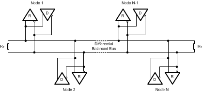
The M-LVDS standard specifies electrical characteristic of line drivers and receivers intended for general data transport over a multipoint bus (Figure 2-1) where up to 32 nodes may be connected. More specifically, it defines driver output characteristics, and input characteristics of two receiver types. The following two sections summarize the key M-LVDS driver and receiver characteristics and compare them to the characteristics of drivers and receivers conforming to the two other popular differential standards: RS-485 (TIA/EIA-485-A) and LVDS (TIA/EIA-644-A).
 Figure 2-1 Multipoint Network