SNLA113C november 2008 – june 2023 DS91M124 , DS91M125 , SN65LVDM050 , SN65LVDM050-Q1 , SN65LVDM051 , SN65LVDM051-Q1 , SN65LVDM1676 , SN65LVDM1677 , SN65LVDM176 , SN65LVDM179 , SN65LVDM180 , SN65LVDM22 , SN65LVDM31 , SN65MLVD040 , SN65MLVD047A , SN65MLVD048 , SN65MLVD080 , SN65MLVD082 , SN65MLVD128 , SN65MLVD129 , SN65MLVD2 , SN65MLVD200A , SN65MLVD202A , SN65MLVD204A , SN65MLVD204B , SN65MLVD206B , SN65MLVD3
- 1
- AN-1926 An Introduction to M-LVDS and Clock and Data Distribution Applications
- Trademarks
- 1 Introduction
- 2 M-LVDS Standard Overview
- 3 Driver Characteristics
- 4 Receiver Characteristics
- 5 M-LVDS Portfolio
- 6 M-LVDS Applications
- 7 Clock Distribution in AdvancedTCA Systems
- 8 Clock Distribution in MicroTCA Systems
- 9 M-LVDS as a Short Reach RS-485 Alternative
- 10Signal Distribution with Point-to-Point Links
- 11Wired-OR Implementation
- 12Design Guidelines
- 13Conclusion
- 14References
- 15Revision History
9 M-LVDS as a Short Reach RS-485 Alternative
While RS-485 multipoint differential busses are long reach and typically implemented with cables as transmission media, M-LVDS devices have found applications in backplane environments. Multipoint links that utilize cables as interconnects are possible with M-LVDS as well. However, system designers need to pay extra attention to stub lengths, bus impedance, and potential differences between nodes. Making stubs as short as possible, spacing the loads evenly, and ensuring less than ±1V of potential difference between the nodes enables robust designs of M-LVDS multipoint networks outside the backplane arena.
Another common application space that RS-485 and M-LVDS interfaces share is a point-to-point signal transmission over cables. When it comes to driving signals over long cables, a larger swing of RS-485 and especially wider input common mode range do help to achieve longer transmission distances; however, M-LVDS devices have the advantages of higher speed, lower power consumption and lower EMI. These key M-LVDS characteristics are beneficial in many applications.
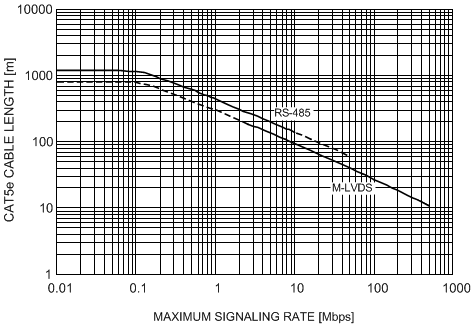
Figure 9-1 shows a typical CAT5e cable length as a function of bit rate for the RS-485 and M-LVDS point-to-point links. The sloped portion of the RS-485 curves is determined based on the maximum attenuation of 9 dB at the frequency of 1/tUI in hertz, where tUI is a unit interval at a given signaling rate. This is an accepted industry guideline for determining maximum signaling rate for the RS-485 point-to-point links. The flat portion of the RS-485 curve is based on the ohmic loss of a typical CAT5e cable (9Ω / 100m).
For networks that use low voltage differential drivers (M-LVDS, LVDS), the maximum attenuation of 6 dB at 1/tUI hertz may be used as a general guideline when determining maximum signaling rate for a given cable length. The guideline assumes dc-balanced data, point-to-point links, zero crosstalk and pair-to-pair skew, and no external interference. Note the dashed portion of the M-LVDS curve. In theory, M-LVDS interfaces can transmit sub-Mbps signals over hundreds of meters of CAT5e cable, however, M-LVDS receivers can only handle ±1V of ground noise. System designers building M-LVDS interfaces over long cables need to ensure that the ground noise does not exceed the ±1V limit or they need to fully eliminate the DC component of signals by implementing either AC-coupled or transformer-coupled interfaces.
 Figure 9-1 CAT5e Length as a Function of Bit Rate for M-LVDS and RS-485 Point-to-Point Links