SNOAAA5 April 2024 DRV8220 , FDC1004-Q1 , LDC3114-Q1 , TMAG5131-Q1 , TMAG5173-Q1 , TMAG6180-Q1
- 1
- Abstract
- Trademarks
- 1Introduction
- 2Automotive Door Handle Architectures
- 3Functional Demo Design
- 4Detailed Design Flow for Door Handle Functions
- 5Summary
- 6References
4.3.1 Overview of Capacitive Sensing Applications
Capacitive sensing is a technology that senses the distortion of a sensor electrode's electric field by an external target (object to be measured). The sensor electrode is frequently a conductive structure (like a copper plate) that radiates an electric field onto the target, forming a mutual capacitance between the sensor electrode and the target. The capacitive sensor device (in this case the FDC1004) detects the capacitance change, and provides output data that reflects the new capacitance value.
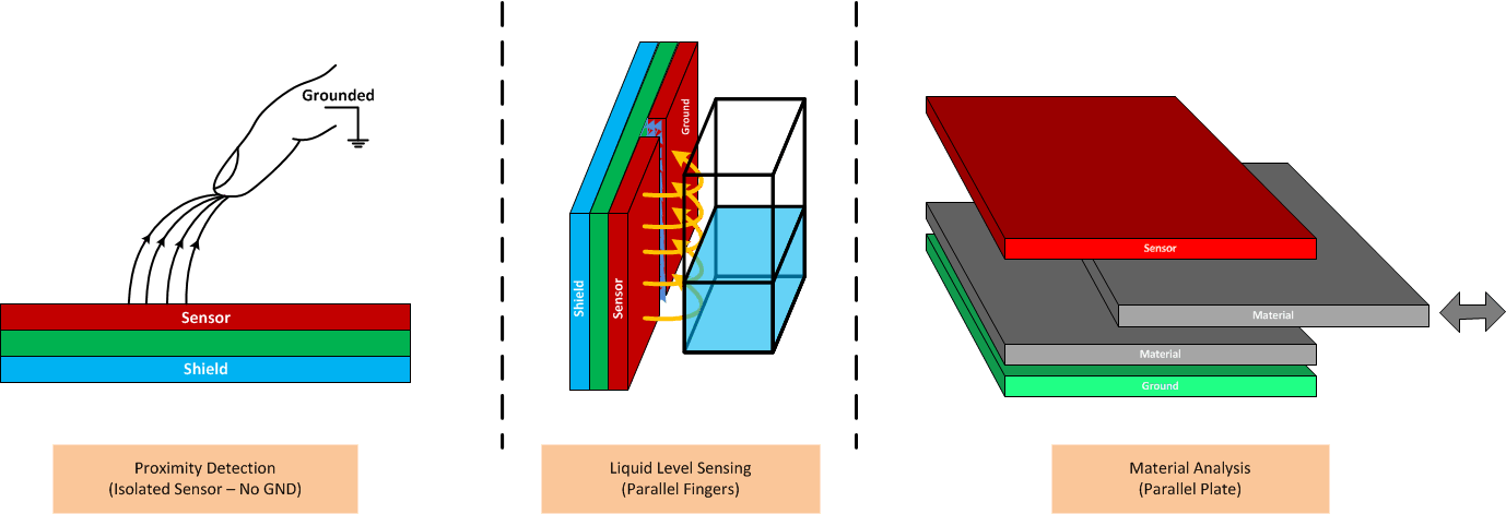
Figure 4-14 illustrates how capacitive sensing can be used in proximity detection, liquid level sensing, and material detection. In proximity detection - emphasized in this application note - a grounded, conductive object, like the finger shown in the left diagram, is effectively a ground plane and forms a mutual capacitance with the sensor. As the finger moves toward or away from the sensor, the capacitance changes, which is then detected by the capacitive sensing device. In liquid-level sensing, the positions of the sensor and target (the liquid) are fixed, and the changes in liquid level cause the sensor or liquid capacitance to change, which is detected by the device. In material detection, the sensor and target can have fixed size and positions, and the sensor or target capacitance can help distinguish different materials through the target materials' permittivity (εt = εrεo) and the impact on capacitance. For more detailed information, please see FDC1004: Basics of Capacitive Sensing and Applications.
 Figure 4-14 Capacitive Sensing Applications
Two challenges with capacitive sensing are interference from nearby objects and electromagnetic (EM) energy in the surrounding environment. Both can frequently be managed by sound mechanical design and the use of active shields. Active shields offer an advantage over grounded shields in that they can be positioned close to the sensor for maximum protection without adversely loading the sensor and overwhelming the measurement of the target's capacitance. Unlike grounded shields, which are by definition held at zero voltage, active shields are driven with the same waveform as the sensor, so there is no voltage difference between the sensor electrode and the active shield. The zero voltage difference between the sensor and shield waveforms will avoid loading of the sensor by the nearby shield. The low output impedance of the shield driver will attenuate external EM fields incident on the shield, and isolate the sensor from nearby objects. The active shield will help focus the region of detection to the unshielded side of the sensor.
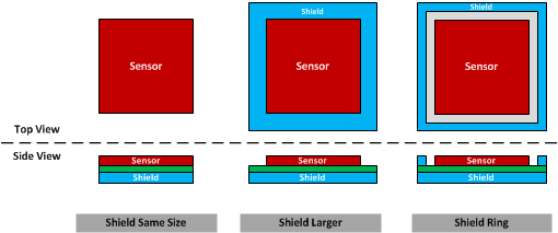
A shield electrode can be paired with the sensor electrode in several ways, as shown in Figure 4-15.
- A shield the same size as the sensor electrode placed directly underneath the sensor.
This configuration represents the minimum shield size that needs to be used.
- A shield larger than the sensor electrode placed directly underneath the sensor. Compared to same-size sensors, this provides better attenuation of interference from sides below the sensor
- A shield ring wrapped around the top side adjacent to the sensor with a shield underneath the sensor. This provides the best attenuation of interference originating from below and to the sides of the sensor.
The distance between the sensor and shield electrode needs to be minimized to make sure the best attenuation of interference with respect to the sensor electrode.
 Figure 4-15 Active Shield Configurations
Note that PCB traces connected to the sensor electrode can also be sensitive to interference. Depending on the design and PCB layout, it may be possible to shield the PCB traces that connect to the sensor, thereby attenuating interference on the traces. For more detailed information, please see Capacitive Sensing: Ins and Outs of Active Shielding.
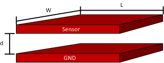
The designs of the sensor electrode can vary widely, and are often dependent on the mechanical constraints of the system. General guidelines are difficult to provide, and a final sensor design can frequently come down to trial-and-error and perhaps (but not always) EM simulations. A good starting point for a touch detection application is to consider the well-known equation for a designed for parallel-plate capacitor:
Where:
- A = area of the two plates (meters2)
- εr = relative permittivity of the material between the two plates
- ε0 = permittivity of free space, 8.85 x10⁻¹² F/m
- d = separation distance between the plates (meters)
 Figure 4-16 Parallel Plate Capacitor
A good starting point is to consider the available sensor area due to mechanical requirements, and use Equation 2 to approximate the resulting capacitance. For a car door handle in resting position (for example, with no nearby hand), the sensor electrode could have curvature or contours, and the effective ground plane could be a combination of surfaces with different distances, making straightforward calculations difficult. Add to this the fact that other materials - with permittivity (εT = εrε0) - can be positioned between the sensor and ground electrodes, as could moisture and other contaminants, and all of these can affect the capacitance. This inactive state can be important because it establishes the nominal, resting capacitance of the sensor.
If the car door handle is being activated, the nearby hand needs to be the dominant ground surface, and can have more or less area than the sensor. If the area of the hand or fingers is larger than the sensor, then Equation 2 offers a sound approximation. If the hand or finger area is less than the sensor, then the actual sensor capacitance can likely be less than predicted by the equation.
More detailed information is available in the Capacitive Proximity Sensing Using the FDC1004, application note.