SNOAAA5 April 2024 DRV8220 , FDC1004-Q1 , LDC3114-Q1 , TMAG5131-Q1 , TMAG5173-Q1 , TMAG6180-Q1
- 1
- Abstract
- Trademarks
- 1Introduction
- 2Automotive Door Handle Architectures
- 3Functional Demo Design
- 4Detailed Design Flow for Door Handle Functions
- 5Summary
- 6References
3 Functional Demo Design
The functional prototype shown in Figure 3-1 was built to demonstrate how some of the aforementioned functions are achieved within door handle systems: deployable door handle position detection using the TMAG6180-Q1, door open/closed detection using the TMAG5131-Q1, and hand proximity detection and soft touch detection using the FDC1004-Q1.
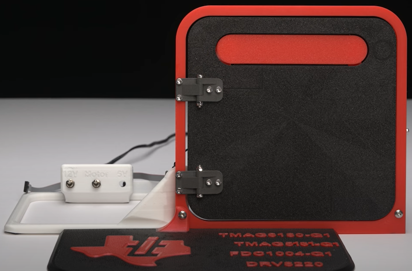 Figure 3-1 Front View of Door Handle Demo
The front-view of the demo shows the 3D printed door frame, door and hinges, deployable door handle, power switches, and base plate. The leftmost switch controls the 12V power to the demo. The middle switch interrupts the output from the motor driver going to the motor. The rightmost switch is included for future implementation of interrupting the 5V line from USB.
The rear view of the demo in Figure 3-2 shows a DRV8220EVM is connected to a 227:1 Metal Gearmotor 25Dx56L mm MP 12V that extends the handle via a motor arm. The DRV8220 was selected because it supports phase or enable control and has a relatively small form-factor EVM. A buck converter soldered onto a proto board beside the DRV8220EVM steps the 12V source down to 5V to power the TI-SCB. The TI-SCB then uses an LDO to produce 3.3V. The buck converter allows the demo to operate with only the 12V source, not needing to be plugged into a computer.
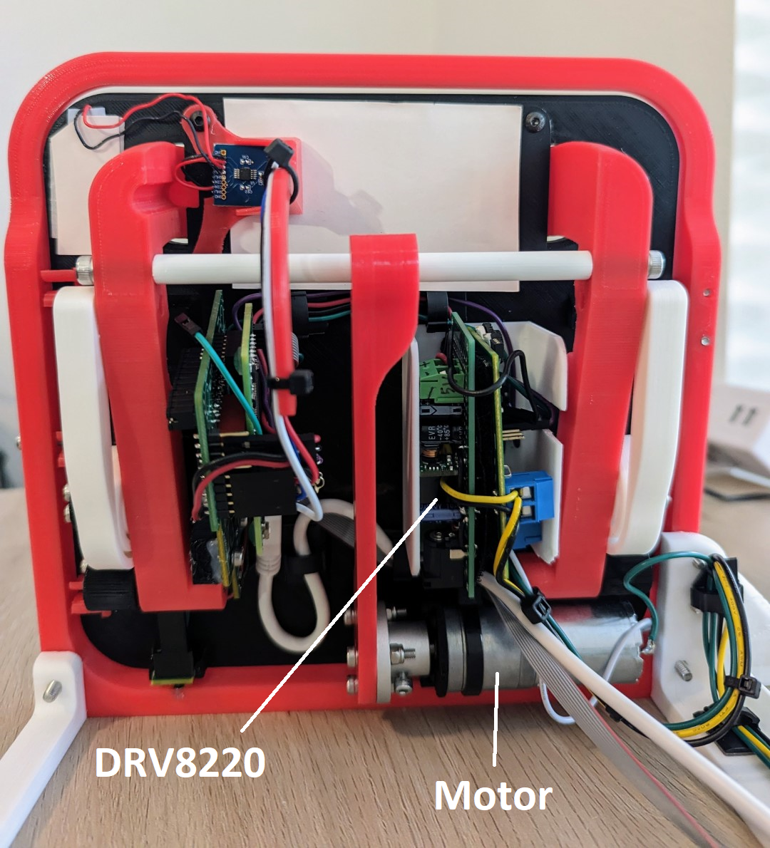 Figure 3-2 Rear View of Door Handle Demo
A pair of 3D printed torsion springs help return the handle to the home position after being pressed or pulled, as shown in Figure 3-3. Using springs to pull the handle back instead of the motor helps prevent a pinch hazard.
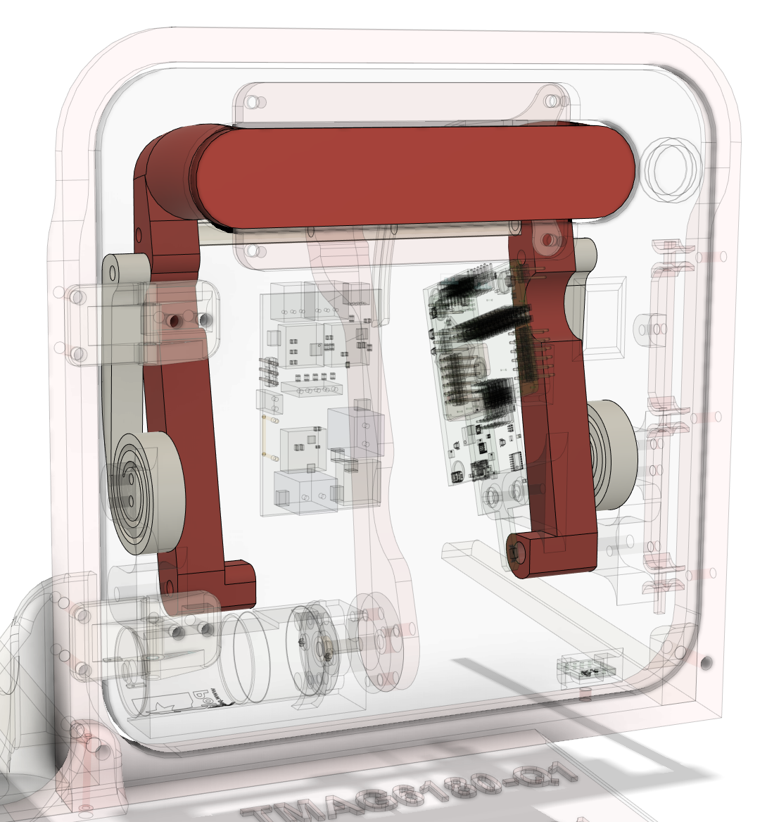 Figure 3-3 Door Handle and 3D Printed Springs
Figure 3-4 shows the TMAG6180-6181EVM and TI-SCB are mounted on the back-side of the door, and a diametric cylinder magnet is embedded in the handle such that the magnet rotates as the handle rotates.
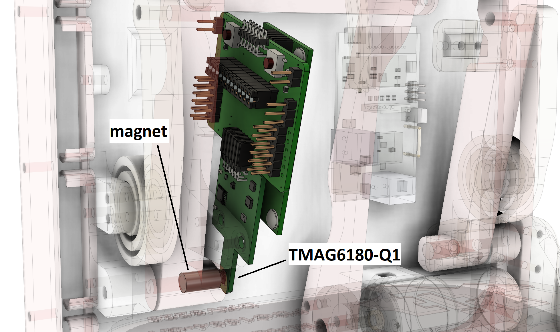 Figure 3-4 TMAG6180-6181EVM, TI-SCB, and Magnet Embedded in Door Handle
The FDC1004EVM is connected to two capacitive sensors made out of layered copper tape as shown in Figure 3-5.
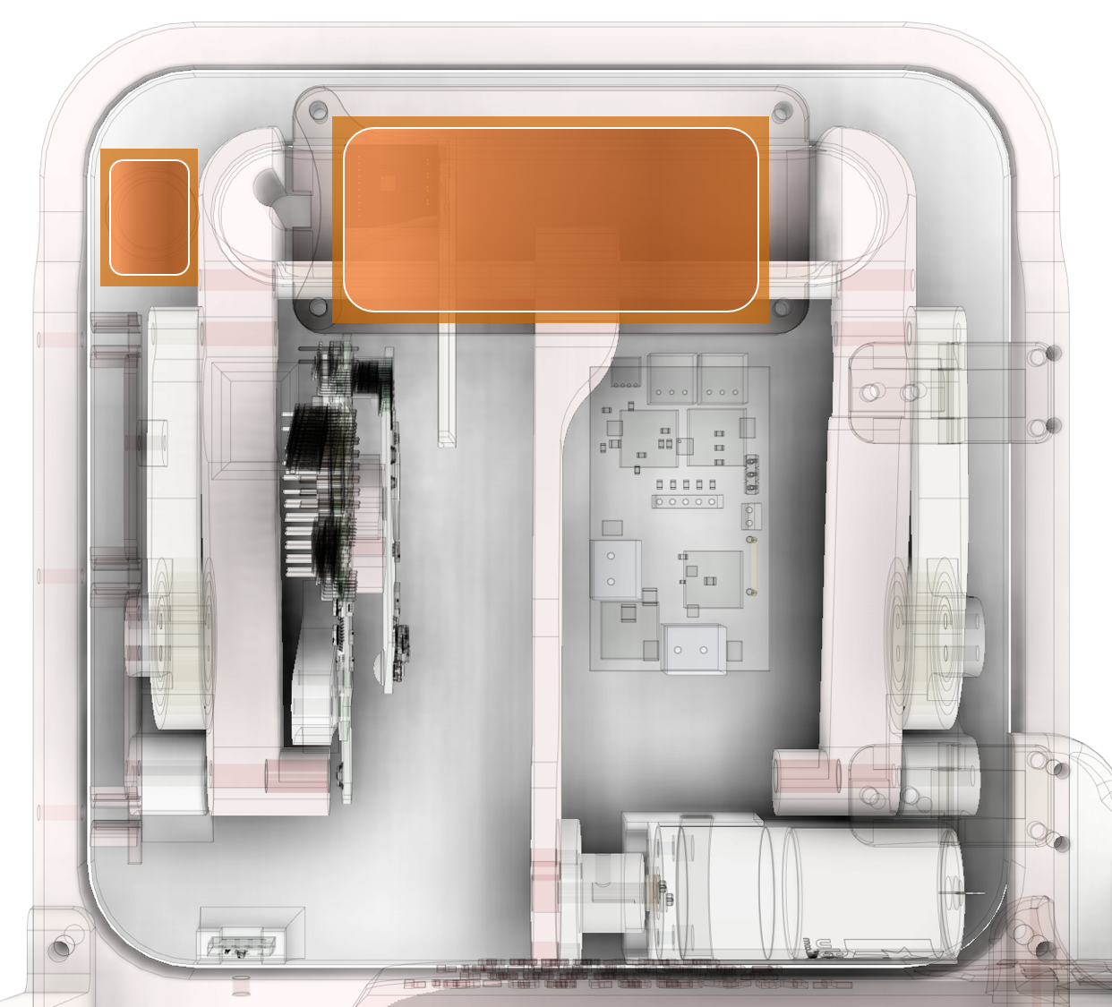 Figure 3-5 FDC1004-Q1 and Capacitive Sensors
Figure 3-6 shows the TMAG5131-Q1 mounted on a HALL-HINGE-EVM board at the bottom of the door, with a small axial cylinder magnet embedded in the door frame.
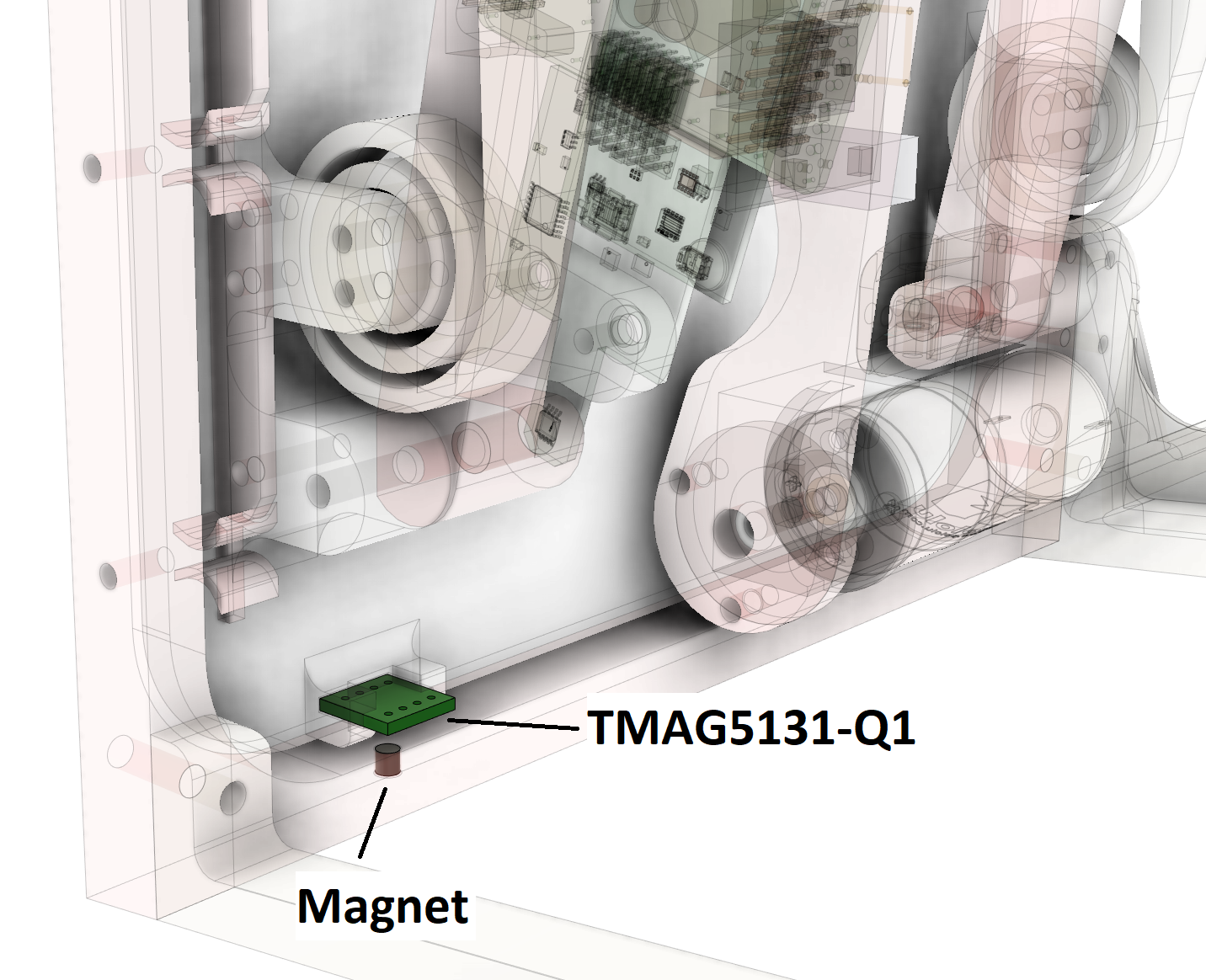 Figure 3-6 TMAG5131-Q1 and Magnet Embedded in Door Frame