SNOAAA5 April 2024 DRV8220 , FDC1004-Q1 , LDC3114-Q1 , TMAG5131-Q1 , TMAG5173-Q1 , TMAG6180-Q1
- 1
- Abstract
- Trademarks
- 1Introduction
- 2Automotive Door Handle Architectures
- 3Functional Demo Design
- 4Detailed Design Flow for Door Handle Functions
- 5Summary
- 6References
4.1 Door Open or Closed Detection With Magnetic Sensing
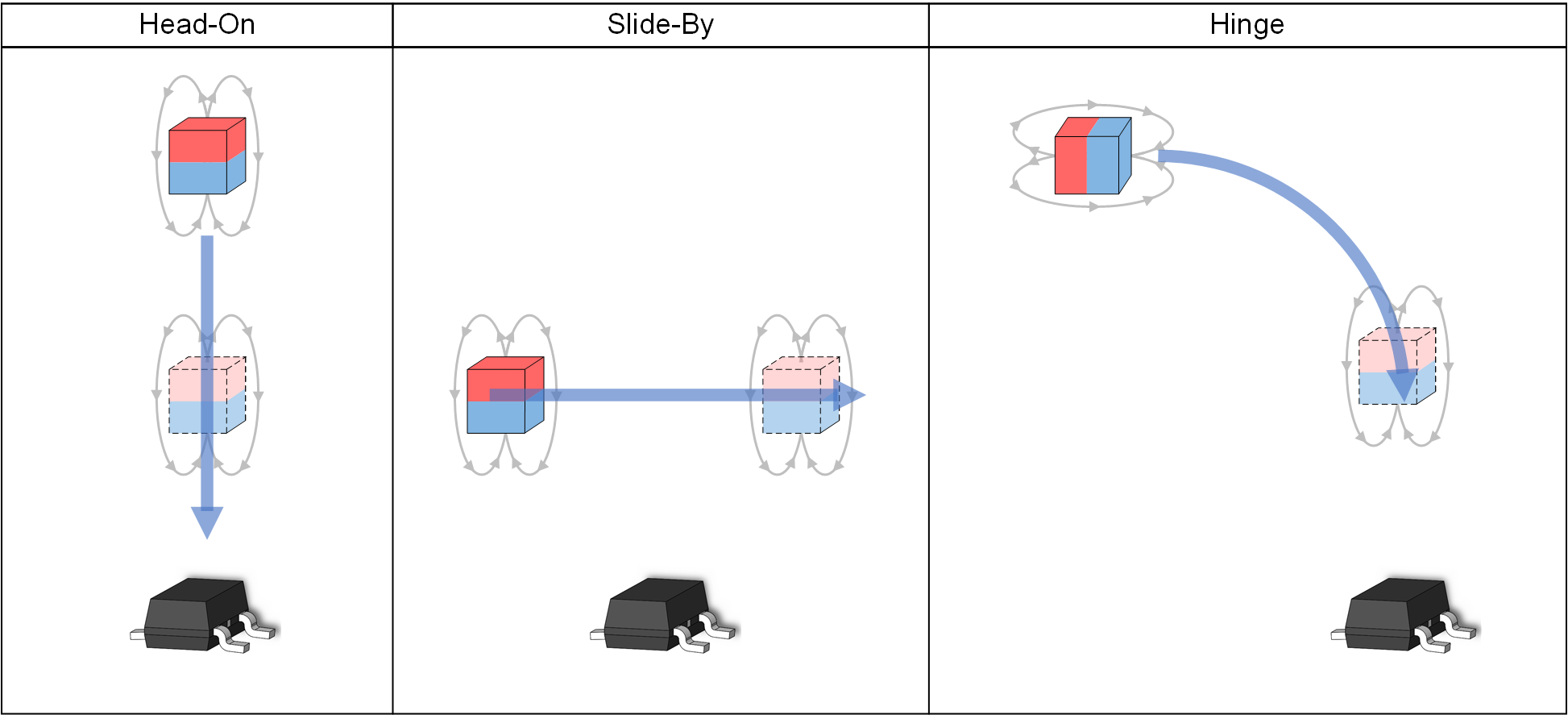
Hall-effect switches are commonly used in transition detection applications, as shown in Figure 4-1. The opening and closing of a car door most resembles the hinge motion, where the magnet swings toward or away from the sensor.
 Figure 4-1 Examples of Transition Detection Design Implementations
The magnetic implementation of this function involves embedding the magnet in the door such that the magnet moves in a hinge type motion as the door opens and closes. A Hall-effect switch installed in the door frame opposite the magnet and detects the presence or absence of the magnetic field. Omnipolar switches like the TMAG5131-Q1 can trigger for either North or South magnetic fields as shown in Figure 4-2, whereas unipolar switches can only trigger for one polarity.
 Figure 4-2 Omnipolar Hall-Effect Switch Operation
The main objective is to design the system such that the spatial coordinates of the transition region fall within the spatial coordinates associated with the BOP maximum and BRP minimum specifications.
Important variables to consider when implementing transition detection include magnet size and type, Hall-effect switch selection, and the placement of the magnet and the switch. Magnetic simulation tools like TI Magnetic Sense Simulator (TIMSS) help determine these variables and facilitate rapid design iteration.