SNOAAA5 April 2024 DRV8220 , FDC1004-Q1 , LDC3114-Q1 , TMAG5131-Q1 , TMAG5173-Q1 , TMAG6180-Q1
- 1
- Abstract
- Trademarks
- 1Introduction
- 2Automotive Door Handle Architectures
- 3Functional Demo Design
- 4Detailed Design Flow for Door Handle Functions
- 5Summary
- 6References
4.2 Deployable Door Handle Position Detection With Magnetic Sensing
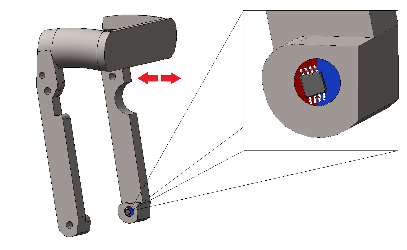
Tracking the position of a deployable door handle as the door handle is extended and retracted can be achieved in several different ways using magnetic sensing. The movement of the handle can be tracked as either linear motion or a rotation motion. For the purposes of this application note, we consider the rotation of the handle on the axis as the handle is extended and retracted, as shown in Figure 4-7.
 Figure 4-7 Door Handle Rotation Motion
A diametric cylinder magnet can be embedded in the deployable door handle such that the magnet is centered and rotates on the same axis as the handle itself. Thus, the angle of the magnet changes as the door handle extends and retracts. An AMR angle sensor or 3D-linear Hall-effect sensor can be placed on-axis with the magnet or off to the side in an off-axis position, as shown in Figure 4-8.
 Figure 4-8 On-Axis vs. Off-Axis Sensor Alignment
The sensor detects the angle of the magnetic field as the magnet rotates. For an accurate angle measurement, the two axes' amplitudes must be normalized. For an on-axis alignment, typically the amplitudes are well-matched, as shown in Figure 4-9. Off-axis topologies often result in an amplitude mismatch between the two axes, as shown in Figure 4-10. Devices like the TMAG5170-Q1 and TMAG5173-Q1 offer an on-chip gain adjustment option to account for amplitude mismatch and mechanical position misalignments.
 Figure 4-9 Sensor Data for 360° Rotation With On-Axis Alignment
 Figure 4-10 Sensor Data for 360° Rotation With Off-Axis Alignment
Depending on what kind of sensor is chosen, the magnetic output signals can be analog or digital signals. With two signals that have well-matched amplitude and are 90° out of phase, the angle can be calculated using the arctangent function shown in Equation 1.
Where:
- θ represents the angle of the magnetic field
- BX represents the magnitude of the X component of the magnetic field vector
- BY represents the magnitude of the Y component of the magnetic field vector
In this example, the X and Y components of the magnetic field vector are used. Depending on sensor placement, it can be appropriate to use the X and Z or Y and Z field components for the angle calculation instead.
Some devices, such as the TMAG5170-Q1 and TMAG5173-Q1, offer an integrated CORDIC that provides full 360° angle position information for both on-axis and off-axis angle measurement topologies. With a reliable and accurate angle measurement from the magnet, changes in the angle are then correlated to the handle position as it deploys, retracts, is pulled or is pushed for proper state detection.