SWRA672 May   2020 AWR6843AOP , IWR6843AOP


  1.   Thermal Design Guide for Antenna on Package mmWave Sensor
    1.     Trademarks
    2. 1 Introduction
    3. 2 mmWave AoP package
      1. 2.1 Thermal Characteristics of the Package
    4. 3 Salient features of AoP EVM
      1. 3.1 Thermal Challenges in Dissipating the Heat
    5. 4 Techniques for Mitigating the Heat Dissipation
      1. 4.1 Reduce the System Level Thermal Resistance
      2. 4.2 Board Size Scaling
      3. 4.3 Heatsink Options
        1. 4.3.1 Sheet Metal Heat Sink
        2. 4.3.2 Heat Sink Details
        3. 4.3.3 Mounting Options
        4. 4.3.4 Thermal Characteristics With the Sheet-Metal Heatsink
      4. 4.4 Heatsink with fins
        1. 4.4.1 Thermal Characteristics With the Heatsink
    6. 5 PCB based thermal improvements
      1. 5.1 Thermal via array
    7. 6 Application and Demos
    8. 7 Summary
    9. 8 Acknowledgment
    10. 9 References

Mounting Options

Heat sink is mounted from the bottom side of the PCB, as TOP side of the PCB has Antennas on package, any metal elements close to the antenna will affect antenna radiation pattern. Hence, care needs to be taken any heat sink metal elements are away from the Antenna regions. Clamps on the heat sink helps in taking heat from the top layer of PCB and spreads it on the bottom side of the PCB on the heat sink uniformly.
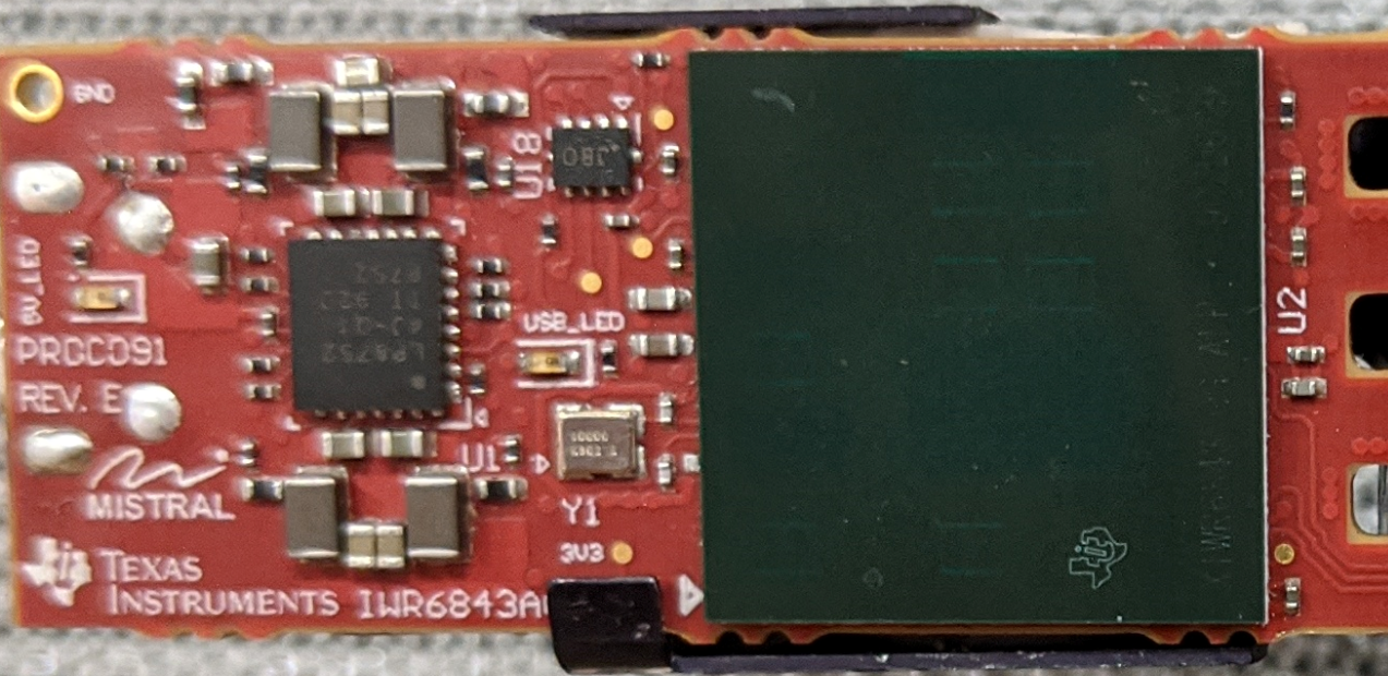
Top_side_of_evm_with_heatsink.pngFigure 9. Top Side of the EVM With Heatsink Mounted
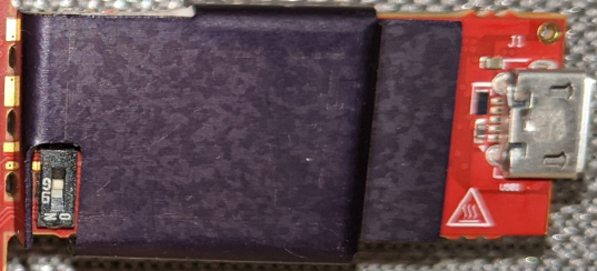
Bottom_side_of_EVM_with_heatsink.pngFigure 10. Bottom Side of the EVM With Heatsink Mounted

Sheet-metal heat sinks are lower cost, easier to manufacture and customize according to board requirements.