SWRA672 May 2020 AWR6843AOP , IWR6843AOP
4.3.4 Thermal Characteristics With the Sheet-Metal Heatsink
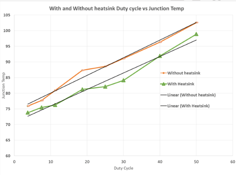
Figure 11 shows measurement of the junction temperature versus duty cycle taken with and without the heat sink. As seen in the plot, EVM can safely operate up to 50% duty cycle.
In this example two cases are taken:
- PCB without using heat sink
- PCB with sheet metal based heatsink.
Figure 11 shows that sheet-metal based heatsink provides improvement in reducing the junction temperature for various duty-cycle conditions.
NOTE
Linear interpolation is plotted for both the cases.
 Figure 11. Thermal Characteristics of mmWave AoP Sensor With and Without Sheet Metal-Based Heatsink
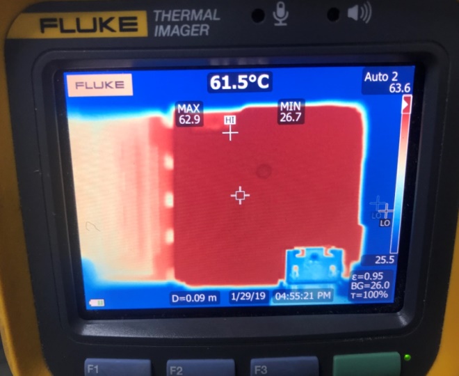
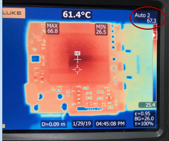
 Figure 12 is the thermal (infrared) image of the board for one of the previous versions of the board with the sheet metal based heatsink. Thermal image clearly showing heat is transferred from the top side of the board to the bottom side of the board and heat is spread uniformly, hence max junction temperature is reduced on top and bottom surface.
 Figure 12. Thermal Imaging of the EVM (top side with heatsink mounted)
  Figure 13. Thermal Imaging of the EVM (bottom side with heatsink mounted)