DLPA059H January 2015 – April 2024 DLP160AP , DLP160CP , DLP2000 , DLP2010 , DLP230NP , DLP3010 , DLP3310 , DLP470NE , DLP470TE , DLP4710 , DLP471NE , DLP471TE , DLP471TP , DLP480RE , DLP550HE , DLP550JE , DLP650LE , DLP650NE , DLP650TE , DLP651NE , DLP660TE , DLP670RE , DLP780NE , DLP780TE , DLP781NE , DLP781TE , DLP800RE , DLP801RE , DLP801XE , DLPA1000 , DLPA2000 , DLPA2005 , DLPA3000 , DLPA3005 , DLPC2607 , DLPC3420 , DLPC3421 , DLPC3430 , DLPC3433 , DLPC3435 , DLPC3438 , DLPC3439 , DLPC4422 , DLPC6401 , DLPC6540
- 1
- Abstract
- Trademarks
- 1 Introduction
- 2 DLP Display Projection Benefits
- 3 What is DLP Technology?
- 4 The DLP Display System
- 5 Selecting the Correct DLP Display Chipset
- 6 How to Evaluate Selected DLP Display Chipset
- 7 Selecting the Correct Optical Engine
- 8 DLP Products Supply Chain
- 9 Development and Manufacturing
- 10Online Resources
- 11Common Display and Projection Terminology
- 12References
- 13Revision History
11 Common Display and Projection Terminology
Table 11-1 provides common display and projection terminology.
| Term | Description |
|---|---|
| Brightness | Brightness is a measure of how much light is perceived by the human eye in a given scene. This is a function of the amount of light (number of photons) and their spread across the color spectrum (photon energy), as well as the varying sensitivity of the human eye across the visible spectrum (most sensitive in the yellow-green region, less sensitive in the blue and red regions). The International System of Units (SI) identifies the lumen as the unit of measurement for brightness |
| Lumens | A DLP projector will often be specified by the number of lumens it is capable of delivering in its projected image. The brightness (lumens) determines how large a screen the projector can create and still be viewable in a given ambient light environment. The greater the brightness, the bigger the displayed image can be made. End products utilizing DLP display technology can range from 20-30 lumens in smartphones and tablets to greater than 50,000 lumens in digital cinema projectors |
| Contrast | The quality of a displayed image is greatly dependent on the distinction between the brightest and the darkest areas of the viewed image. This is quantified by the contrast ratio, which is the ratio of the brightest possible region of the image to the darkest possible region of the image. While the contrast ratio specification of a DLP system is based on system performance, the viewing experience can also be greatly impacted by ambient light. The more ambient light on the screen, the lower the viewable contrast of the image. Together, system contrast and ambient light determine the true viewable contrast of the image. Special attention must be given to the optical design, and quality of optics used in the optical module to maximize contrast. |
| Resolution | The level of detail available in an image is determined by the number of pixels which make up the displayed image. In a DLP system, this is a function of the number of mirrors on the DMD which can represent one or more pixels of the displayed image. Resolution is the number of pixels that can be displayed. The level of detail displayed is not only dependent on the resolution of the projector system but it is also dependent on the resolution of the source content. If the resolution of the source content does not match the resolution of the projector system, the source content is mapped by the controller to make maximum usage of the resolution displayed. DLP display resolutions range from 640 × 360 (nHD) to 3840 × 2160 (4K UHD). |
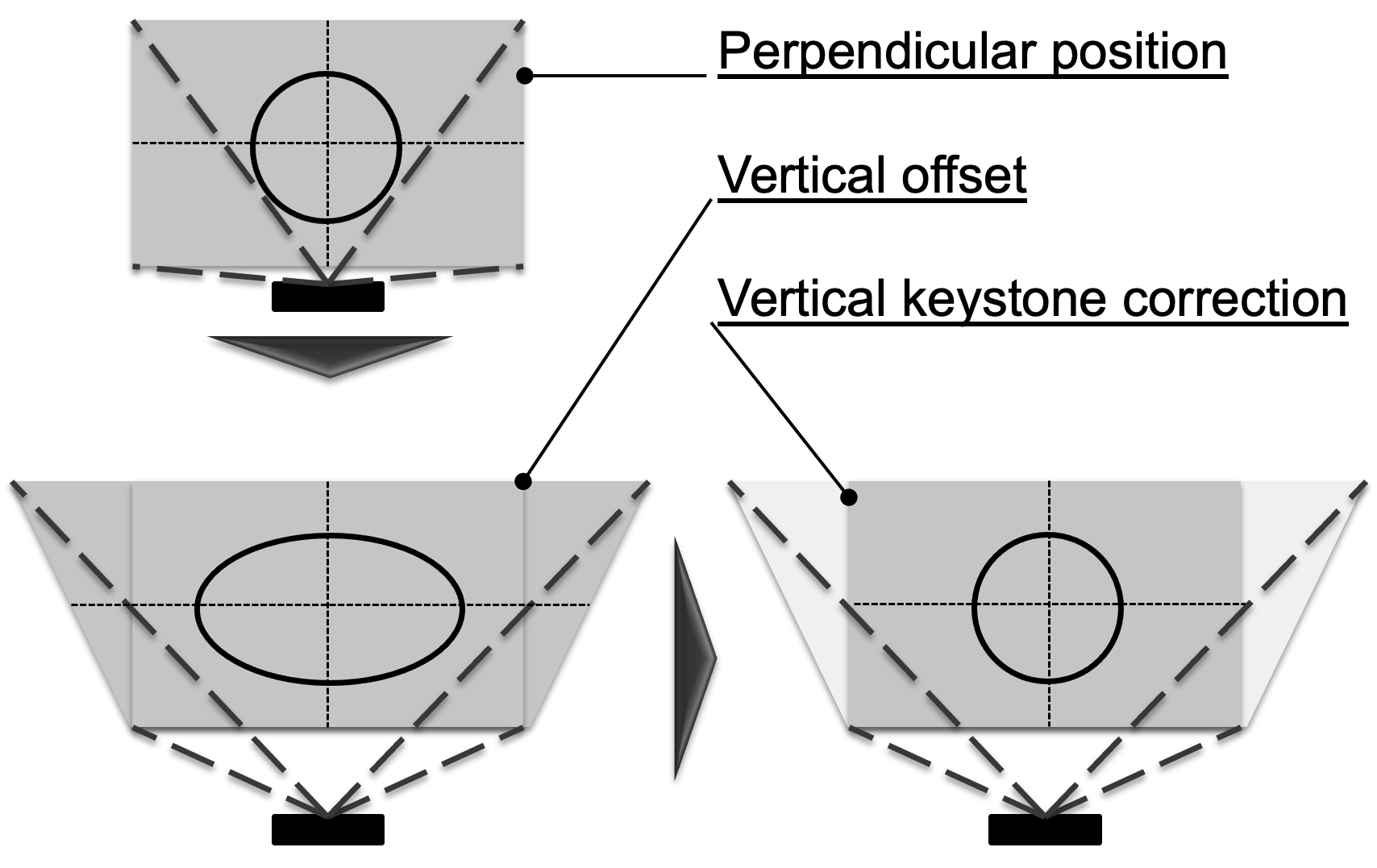
| Keystone | When the optical axis of a
projection system is not perpendicular to the imaging screen, the image
will be geometrically distorted. One of these distortions, caused by the
different distance to the screen top and bottom, is called keystone
distortion. The resulting image will have a different width from top to
bottom, giving the image the shape of an architectural keystone (used at
the top of an arch). This distortion can be avoided by keeping the
projection axis perpendicular to the screen. However, this is sometimes
unavoidable. The keystone distortion can be corrected optically (very
difficult, cost prohibitive, not adjustable) or by image processing
means. DLP controllers provide keystone correction by re-mapping the
input image to the DMD array in such a way as to produce a rectangular
image at the screen. The keystone correction feature is commonly paired
with an accelerometer in the system to automatically adjust the image as
the projector is tilted up and down.  Figure 11-1 Vertical
Keystone Correction
 |
| Color sequential display | DLP DMDs are made up of micromirrors. They only reflect the light which illuminates them. So, how can a DMD chip reproduce full color images? The secret is in the way the human eye works. The human retina and brain synthesizes perceived color by means of a short-term time averaged differential response to the quantity of light impinging on the 3 types of retinal cones (red sensitive, green sensitive, blue sensitive). Since the eye continuously averages the light striking the retina over a period of about 1/50 second, it is possible to illuminate the eye sequentially at a sufficient rate with red, green, and blue images such that the viewer perceives the impression of full color images. This is achieved by a DLP optical module by sequentially turning the R, G, B light sources on and off such that there is, for example, a red image, followed by a green image, followed by a blue image. |
| Front projection / rear projection and screens | A DLP display system uses an optical system to produce a real image of the pixel pattern displayed on the DMD. In order for the projected image to be seen by viewers, the light must be scattered off a surface co-located with the plane of image focus. This function is provided by a screen, which may be a specially optimized sheet of material, or simply a wall, floor, or counter top – any smooth, light colored surface can make a great image. In a front-projection system, the screen must be a reflective surface. A rear-projection system requires a translucent, dispersive screen. In both cases the viewer focuses their eyes on the screen in order to see the projected image. There are some display systems which work by producing a virtual image. For example, near eye displays and heads-up displays create images that are only formed after the light travels through the eye onto the retina |
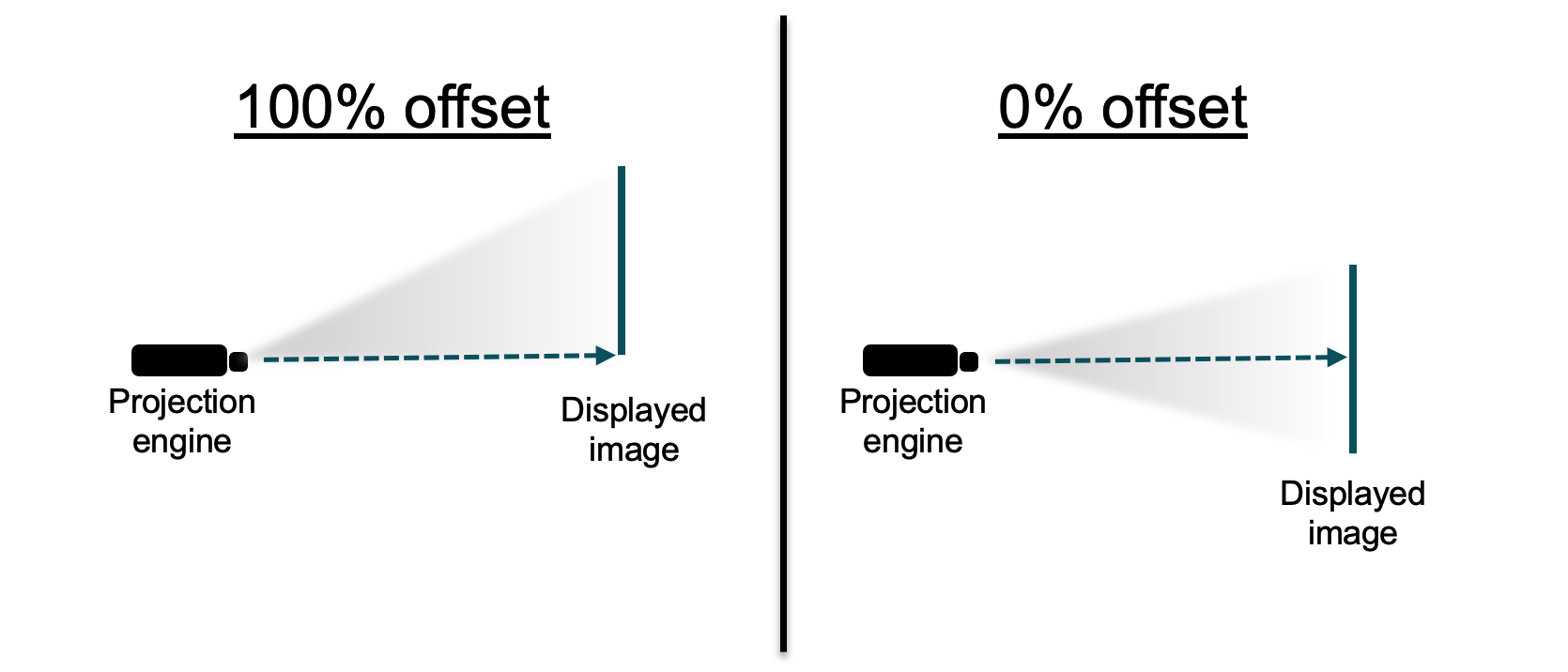
| Offset | The DMD in many DLP
projectors is offset to a position below the optical axis of the
projection lens in order to shift the image above the horizontal plane.
This is useful when the projector is placed on a table to avoid cutting
off the bottom of the projected image. The offset also avoids the
distortion of the image which would occur if the projector was simply
tilted up. Figure 11-2 Offset Effect
on Projected Image
 |
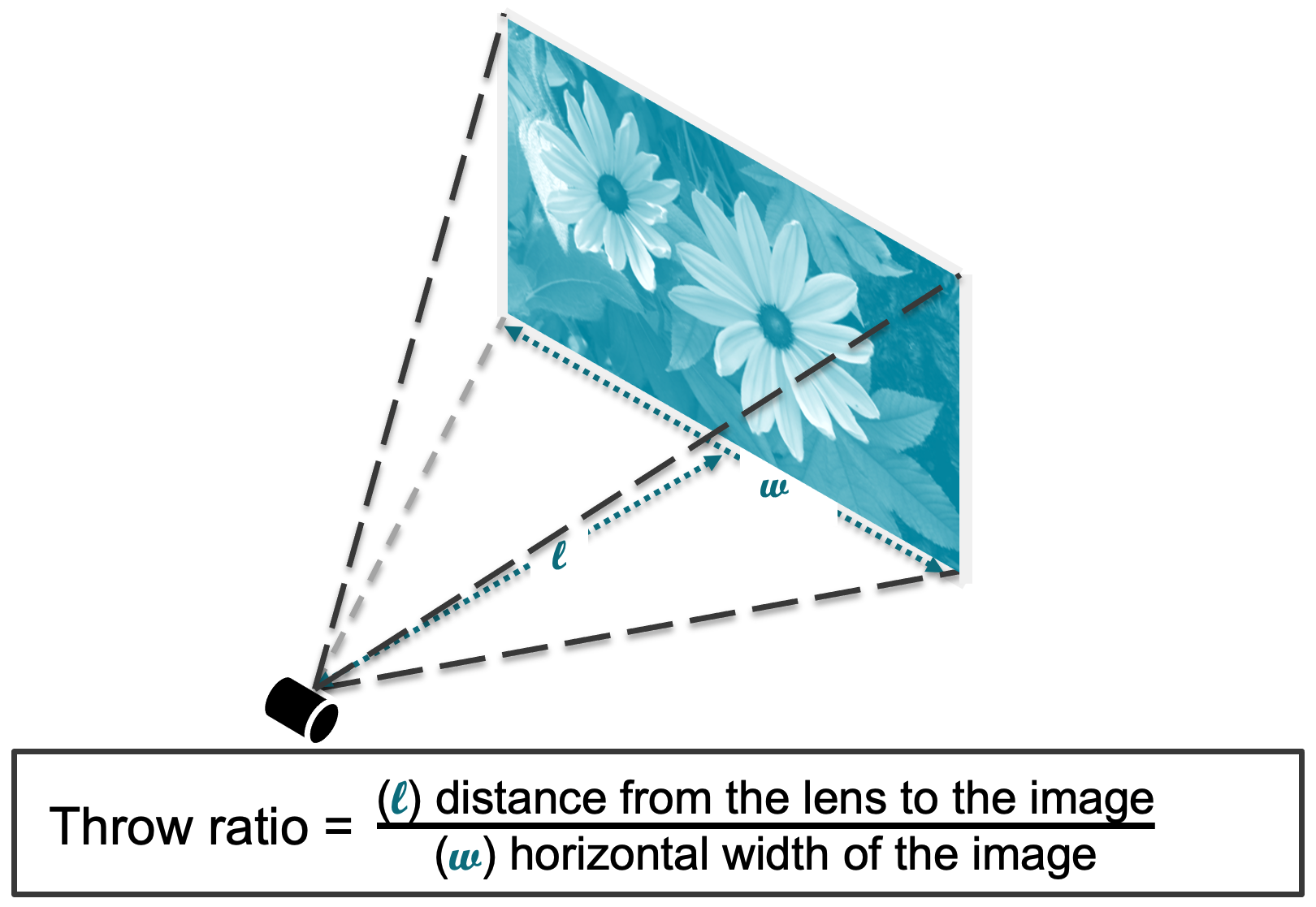
| Throw ratio | In many projection
applications, the placement of the projector with respect to the viewing
screen is important. The throw ratio of the projector determines how far
away the projector must be placed in order to achieve a certain screen
size. The width of the projected image (W) with respect to the distance
from the lens to the center of the screen (D) is the throw ratio (T). Common references to throw ratio: standard throw: throw ratio>1; short throw (ST): 1>throw ratio>0.4; ultra short throw (UST): throw ratio<0.4.  Figure 11-3 Throw Ratio
Diagram
 |
| F-number | The relative brightness of a projected image is a function of both the brightness of the illumination system and the aperture of the lens – that is, the width (D) of the lens opening with respect to the focal length (f) of the lens (determines the size of the projected image). This is expressed as a value called the F-number (N). N = ƒ/D. The relative brightness (rb) of two lenses is a function of square of the inverse ratio of their f-numbers. rb= (N2 / N1)2. For example, a lens of N1=2 is 4x brighter than a lens of N2=4. f-number impacts the system as a tradeoff between brightness and volume (dimensions). Higher f-number (N=2.4) systems are thinner, but may sacrifice brightness compared to a system with lower f-number (N=1.7) depending on its Etendue (typically applicable to LED systems). |
| DLP chipset nomenclature | It is common to refer to the
DLP chipset by its active array diagonal, resolution, and portfolio as
follows: [Array diagonal in inches] [resolution] DLP [Standard or Pico] chipset Example: .47 1080p DLP Pico chipset, refers to the DLP Pico chipset that has .47-inch diagonal active array that supports 1080p on-screen resolution. Table 4-1 provides a high level overview of the DLP chipset part number nomenclature for the DMD, DLP display controller, and DLP PMIC. |