DLPA059H January 2015 – April 2024 DLP160AP , DLP160CP , DLP2000 , DLP2010 , DLP230NP , DLP3010 , DLP3310 , DLP470NE , DLP470TE , DLP4710 , DLP471NE , DLP471TE , DLP471TP , DLP472NE , DLP472TE , DLP480RE , DLP550HE , DLP550JE , DLP650LE , DLP650NE , DLP650TE , DLP651LE , DLP651NE , DLP660TE , DLP670RE , DLP780NE , DLP780TE , DLP781NE , DLP781TE , DLP800RE , DLP801RE , DLP801XE , DLPA1000 , DLPA2000 , DLPA2005 , DLPA3000 , DLPA3005 , DLPC2607 , DLPC3420 , DLPC3421 , DLPC3430 , DLPC3433 , DLPC3435 , DLPC3438 , DLPC3439 , DLPC6401 , DLPC6540
- 1
- Abstract
- Trademarks
- 1 Introduction
- 2 DLP Display Projection Benefits
- 3 What is DLP Technology?
- 4 The DLP Display System
- 5 Selecting the Correct DLP Display Chipset
- 6 How to Evaluate Selected DLP Display Chipset
- 7 Selecting the Correct Optical Engine
- 8 DLP Products Supply Chain
- 9 Development and Manufacturing
- 10Online Resources
- 11Common Display and Projection Terminology
- 12References
- 13Revision History
4.3 Optics
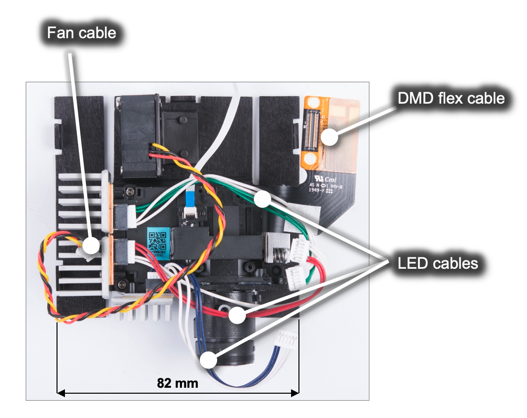
The DMD, along with its associated electronics, an illumination source, optical elements, and necessary mechanical components, are combined into a compact and rugged assembly known as an optical module or light engine (Figure 4-4). The optical module is the core display component of the system. Optical modules can be of various sizes depending on the application and requirements. In general, the higher the brightness, the larger the size of the optical module due to the use of larger illumination sources, optics, DMDs, and thermal management components such as heat sinks and fans.
The optics portion of the display hardware system starts with electric signals going into an optical module housing that include all the components needed to create a projected image. General information about optical modules are located here for DLP Pico chipsets and here for DLP standard chipsets.
The DMD is connected to the DLP Pico controller by a flex cable or board-to-board connector. The LEDs in the optical module are connected with wires to the DLP PMIC (LED driver). System boards, fans, heat sinks, mechanical parts, switches, and other parts are assembled into a compact and robust final product around the optical module.
 Figure 4-4 DLP Pico .23 1080p (DLP230NP)
Display Optical Engine
Figure 4-4 DLP Pico .23 1080p (DLP230NP)
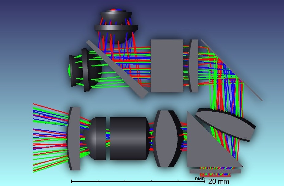
Display Optical EngineFigure 4-5 shows the optical components that can be included in an optical module. Click here to watch a video of an example optical module reference design (.23 qHD DMD; DLP230GP). Keep in mind that details of an optical module may not be relevant for a company that is planning to source a mass production optical engine. To read an application note that covers in detail how to specify an optical module, see TI DLP® Pico™ System Design: Optical Module Specifications. Also, click here to search for optical modules in mass production available for purchase. Figure 4-5 shows an optical module design example from DLP2010 DMD Optical engine reference design.
 Figure 4-5 .2 WVGA (DLP2010) Optical
Module Example
Figure 4-5 .2 WVGA (DLP2010) Optical
Module Example| Components | Description |
|---|---|
| DMD | The digital micromirror
device is the component that houses the active digital micromirror
array, which allows the creation of a color plane, which enables the
projected image in combination with the illumination source. Each
DMD has the following unique characteristics:
|
| DMD mounting mechanism |
The mounting of the DMD includes several needs: (a) proper placement of the DMD’s active array relative to the optical axis of the application, (b) a dust-proof seal between DMD and the optical assembly chassis, (c) reliable electrical connection, and (d) proper thermal management. to learn more about mounting concepts for various DLP chipsets, see Mounting Hardware and Quick Reference Guide for DLP® Advanced Light Control DMDs. |
| DMD flex cable |
Cable used to transport electrical signals between the DMD and the display controller. |
| Illumination source (color mechanism) |
DLP technology is
illumination source agnostic. The illumination sources that are
broadly available today are RGB LED and laser phosphor. RGB LED illumination. This illumination scheme uses red, green, and blue LEDs displayed with a single-color plane refresh rate. In some cases, a fourth LED will be used to increase brightness, although this brightness increase is penalized heavily against power efficiency. A 3-channel architecture could support brightness efficiency over 20 lumens/Watt (lm/W), while a 4-channel architecture will support brightness efficiency lower than 10 lm/W. Laser phosphor illumination. This illumination approach uses a single blue laser source diffused in combination with one or two phosphor color wheels to provide RGB light sources. Some implementations add a red or green channel to boost color performance. RGB Laser illumination. This illumination approach uses red, green, and blue laser sources. A de-speckler optical element is typically used for this implementation to improve image quality, although it is not required. |
| Optical actuator (if needed) |
The DMD fast speed
allows a use of an optical actuator. 2-way and 4-way actuators that
meet TI specifications are used to increase on-screen resolution
while retaining the optical benefits of a 5.4μm pixel node. 2-way actuator, products like the DLP Pico .33 1080p (DLP3310) use a 2-way actuator to double the on-screen resolution of the DMD active array. 4-way actuator, products like the DLP Standard .47 4K (DLP471TE) use a 4-way actuator to quadruple the on-screen resolution of the DMD active array |
| Homogenizer | The function of the homogenizer is to make the intensity profile of the light source to be more uniform. Typically, a fly’s eye array or light tunnel are used for this purpose. The optical element is located between the illumination source and the DMD. |
| Projection lens | The purpose of the projection lens is to magnify the image coming from the DMD to the display surface. It also determines the throw ratio, defined as the distance between the projection lens and the display surface divided by the width of the displayed image. It also determines the image offset of the projection lens relative to the display surface. Watch this video to learn more about throw ratio and image offset. |
| Illumination projection interface |
This optical element is responsible to interface between the DMD and projection optics. A few options include field lens, non-telecentric, total internal reflection (TIR) prism, and reverse TIR (RTIR) prism. |
| Thermal management | To ensure the proper operation of the optical module, it is important to consider thermal management for the DMD and the illumination sources. Watch this video to see an innovative example of thermal management for a very small projection-based smart display. |
Watch this video to get more details on common projection lens specifications, including throw ratio definition, offset definition, and telecentric and non-telecentric architecture comparison.