SBAA383C January 2020 – January 2024 TLV320ADC3120 , TLV320ADC3140 , TLV320ADC5120 , TLV320ADC5140 , TLV320ADC6120 , TLV320ADC6140
4 Configuring PurePath Console for Multiple TLV320ADCx140/PCMx140-Q1 EVMs
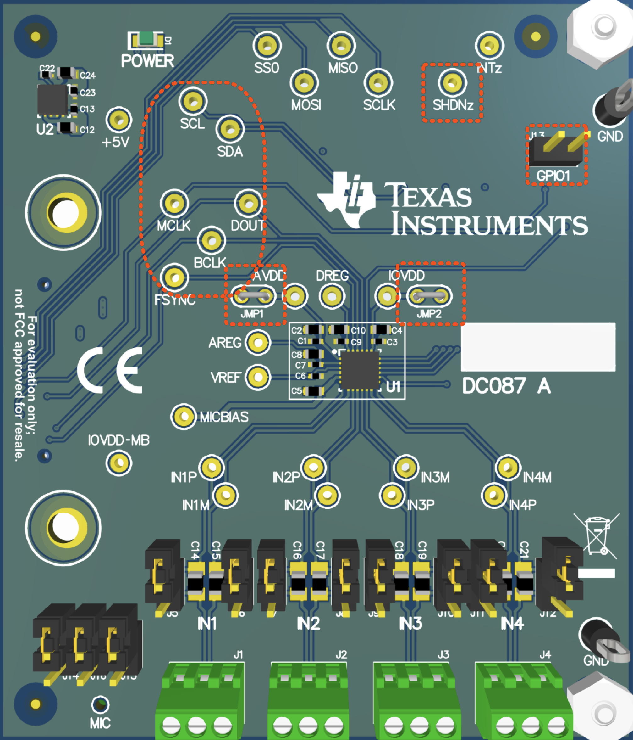
The PurePath™ Console supports multiple TLV320ADCx140/PCMx140-Q1 devices connected to a single AC-MB. However, the AC-MB connector can only be connected to one TLV320ADCx140/PCMx140-Q1. To connect additional devices to a single AC-MB, externally wire power, ground, I2C, and TDM signals of the board connected to a single AC-MB to the respective signals of the other TLV320ADCx140/PCMx140-Q1 EVMs. Connect only one EVM to the AC-MB while connecting the other signals through their respective headers or jumpers as follows:
- Connect together IOVDD from all the TLV320ADCx140/PCMx140-Q1 EVMs through the JMP2 jumper.
- Connect together AVDD from all the TLV320ADCx140/PCMx140-Q1 EVMs through the JMP1 jumper.
- Connect together SHDNz from all the TLV320ADCx140/PCMx140-Q1 devices through the SHDNz test point.
- Connect together the SCL pins from all TLV320ADCx140/PCMx140-Q1 devices through the SCL test point.
- Connect together the SDA pins from all TLV320ADCx140/PCMx140-Q1 devices through the SDA test point.
- Connect together the BCLK pins from all TLV320ADCx140/PCMx140-Q1 devices through the BCLK test point.
- Connect together the FSYNC pins from all TLV320ADCx140/PCMx140-Q1 devices through the FSYNC test point.
- SDOUT connections depend on Shared TDM or Daisy-Chain TDM mode:
- For Shared TDM mode, connect together the SDOUT pins from all TLV320ADCx140/PCMx140-Q1 devices through the DOUT test point.
- For Daisy-Chain TDM mode, connect the TLV320ADCx140/PCMx140-Q1 EVMs
in a daisy chain fashion:
- Connect the GPIO1 signal at the header J13, pin1 (GPIO1) from the board connected to the AC-MB to the SDOUT pin of the second board through the DOUT test point.
- Connect the signal of the second board at the header J13, pin1 (GPIO1) to the SDOUT pin of the third board through the DOUT test pin, if using three devices or more.
- Connect the signal of the third board at the header J13, pin1 (GPIO1) to the SDOUT pin of the fourth board through the DOUT test pin, if using four devices.
These signals can be tapped at the respective digital test points of the TLV320ADCx140/PCMx140-Q1 EVMs, as shown in Figure 4-1.
 Figure 4-1 Location of TLV320ADCx140/PCMx140-Q1
EVM I2C and TDM signals