SBAU376A December 2021 – March 2022
- 1
- Abstract
- Trademarks
- 1Overview
- 2Kit Contents
- 3Related Documentation From Texas Instruments
- 4Hardware
- 5EVM Operation
- 6Schematics, PCB Layout, and Bill of Materials
- 7Revision History
5.1.3.2.2 GUI DAC Configuration Page
The DAC on the EVM is configured using the DAC
configuration page on the GUI. When configuring the DAC using the EVM, make sure
that the EVM is configured to set the BOP using the DAC (see Section 4.1.1). To go to the
DAC configuration page on the GUI, click the DAC configuration icon
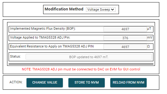
 . Figure 5-10 shows the DAC configuration page.
 Figure 5-10 TMAG5328 GUI DAC Configuration
Page
Figure 5-10 TMAG5328 GUI DAC Configuration
Page- Modification Method Drop-Down Box:
This drop-down box selects which method is used for setting the DAC voltage
after you click the CHANGE VALUE button. There are four modification
methods offered in this drop-down box:
- Voltage sweep
Drop-Down Box Option: This method sweeps the DAC output voltage
to find the sensed magnetic flux density and then sets the
BOP to this sensed magnetic flux density. Completeing the
voltage sweep operation takes 20 seconds. During this time, the screen
in Figure 5-11 is shown. After 20 seconds has passed, the screen in Figure 5-11 disappears and the status text box states one of the following:
- If the operation is successful: "BOP updated to" followed by the sensed magnetic flux density value (see Figure 5-10).
- If the operation was successful but the sensed magnetic flux density was greater than the maximum 15-mT BOP supported by the device: "Magnetic Flux Density > 15 mT device maximum Bop."
- If the operation was successful but the sensed magnetic flux density was less than the minimum 2-mT BOP supported by the device: Magnetic Flux Density < 2 mT device minimum Bop.
- If the
operation was not successful: Sweep started. Next
update in 20 seconds.
 Figure 5-11 DAC
Sweep in Progress Screen
- Manual B Drop-Down Box Option: This allows the user to enter a magnetic flux density into the "Implemented Magnetic Flux Density (BOP)" textbox. When you click the CHANGE VALUE button, the DAC is configured to output the voltage needed to generate the BOP that was input into the "Implemented Magnetic Flux Density (BOP)" textbox.
- Manual V Drop-Down Box Option: This allows the user to enter a DAC output voltage into the "Voltage Applied to TMAG5328 ADJ Pin" textbox. When you click the CHANGE VALUE button, the DAC's output voltage is set to the output voltage that was entered into the "Voltage Applied to TMAG5328 ADJ Pin" textbox.
- Manual R Drop-Down Box Option: This setting simulates applying a resistor on the ADJ pin by applying an equivalent DAC voltage that creates the same BOP as the input provided into the "Equivalent Resistance to Apply on TMAG5328 ADJ Pin" textbox. Any resistors entered into this textbox are not programmed into the DAC until you click the CHANGE VALUE button.
- Voltage sweep
Drop-Down Box Option: This method sweeps the DAC output voltage
to find the sensed magnetic flux density and then sets the
BOP to this sensed magnetic flux density. Completeing the
voltage sweep operation takes 20 seconds. During this time, the screen
in Figure 5-11 is shown. After 20 seconds has passed, the screen in Figure 5-11 disappears and the status text box states one of the following:
- Textboxes
- Implemented Magnetic Flux Density (BOP) Textbox: Displays the TMAG5328 BOP value based on the DAC settings. If the Modification Method drop-down box has the "Manual B" option selected, this textbox is also used to enter the desired BOP to change to.
- Voltage Applied to TMAG5328 ADJ Pin Textbox: Displays the DAC output voltage. If the Modification Method drop-down box has the "Manual V" option selected, this textbox is also used to enter the desired DAC output voltage to change to.
- Equivalent Resistance to Apply on TMAG5328 ADJ Pin Textbox: Displays the resistor that can be applied to the ADJ pin to produce the same BOP produced by the currently set DAC output voltage. If the Modification Method drop-down box has the "Manual R" option selected, this textbox is also used to enter the desired equivalent resistance value to change to.
- Status Textbox: This displays the status associated with pressing different action buttons.
- Action Buttons
- CHANGE VALUE button: When you click this button, the DAC output voltage is changed according to the selected option in the "Modification Method" Drop-Down Box.
- STORE TO NVM button: Pressing this button stores the current DAC output voltage to nonvolatile memory. If the EVM is power cycled, then the DAC is automatically set to the last output voltage stored in nonvolatile memory without requiring the microcontroller performing any reconfigurations steps on the DAC. As a result, the BOP is also retained after the power cycle.
- RELOAD FROM NVM button: Sets the current DAC output voltage to the DAC output voltage that is stored in nonvolatile memory.