SLLA272D February 2008 – May 2021
5 Cable Type
RS-485 applications benefit from differential signaling over twisted-pair cable, because noise from external sources couple equally into both signal lines as common-mode noise, which is rejected by the differential receiver input.
Industrial RS-485 cables are of the sheathed, unshielded, twisted-pair type, (UTP), with a characteristic impedance of 120 W and 22–24 AWG. Figure 5-1 shows the cross-section of a four-pair, UTP cable typically used for two full-duplex networks. Similar cables, in two-pair and single-pair versions, are available to accommodate the low-cost design of half-duplex systems.
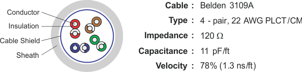 Figure 5-1 Example of RS-485 Communication
Cable
Figure 5-1 Example of RS-485 Communication
CableBeyond the network cabling, it is mandatory that the layout of printed-circuit boards and the connector pin assignments of RS-485 equipment maintain the electrical characteristics of the network by keeping both signal lines close and equidistant to another.