SLLA272D February 2008 – May 2021
9 Data Rate Versus Bus Length
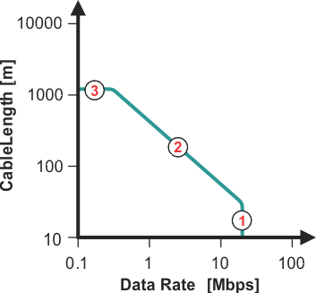
The maximum bus length is limited by the transmission line losses and the signal jitter at a given data rate. Because data reliability sharply decreases for a jitter of 10% or more of the baud period, Figure 9-1 shows the cable length versus data rate characteristic of a conventional RS-485 cable for a 10% signal jitter.

Section 1 of the graph presents the area
of high data rates over short cable length. Here, the losses of the transmission line can
be neglected and the data rate is mainly determined by the driver’s rise time. Although
the standard recommends 10 Mbps, today’s fast interface circuits can operate at data rates
of up to 40 Mbps.
Section 2 shows the transition from short
to long data lines. The losses of the transmission lines have to be taken into account.
Thus, with increasing cable length, the data rate must be reduced. A rule of thumb states
that the product of the line length [m] times the data rate [bps] should be <
107. This rule is far more conservative than today's cable performance and
will therefore show less length at a given data rate than the graph presents.
Section 3 presents the lower frequency
range where the line resistance, and not the switching, limits the cable length. Here, the
cable resistance approaches the value fo the termination resistor. This voltage divider
diminishes the signal by -6 dB. For a 22 AWG cable, 120 W, UTP, this occurs at
approximately 1200 m.
Figure 9-1 Cable Length Versus Data Rate