SLLSFF7B May 2021 – August 2026 ISOW1044
PRODUCTION DATA
- 1
- 1 Features
- 2 Applications
- 3 Description
- 4 Device Comparison Table
- 5 Pin Configuration and Functions
-
6 Specifications
- 6.1 Absolute Maximum Ratings
- 6.2 ESD Ratings
- 6.3 Recommended Operating Conditions
- 6.4 Thermal Information
- 6.5 Power Ratings
- 6.6 Insulation Specifications
- 6.7 Safety-Related Certifications
- 6.8 Safety Limiting Values
- 6.9 Electrical Characteristics
- 6.10 Supply Current Characteristics
- 6.11 Switching Characteristics
- 6.12 Insulation Characteristics Curves
- 6.13 Typical Characteristics
- 7 Parameter Measurement Information
- 8 Detailed Description
- 9 Application and Implementation
- 10Device and Documentation Support
- 11Revision History
- 12Mechanical, Packaging, and Orderable Information
9.2 Typical Application
The ISOW1044 device is designed for applications that have limited board space and desire more integration. The device is also designed for very high voltage applications, where power transformers meeting the required isolation specifications are bulky and expensive. The device can be used in applications with a host microcontroller or FPGA that includes the link layer portion of the CAN protocol. Figure 9-1 shows a typical application configuration for 5V controller applications. The bus termination is shown for illustrative purposes. The ISOW1044 device meets 8kV contact ESD (Electrostatic discharge) per IEC 61000-4-2 standalone with no external components on bus. If the application requires the usage of Common mode choke (CMC), then use of Transient voltage suppressor (TVS) is a must to achieve 8kV IEC ESD.
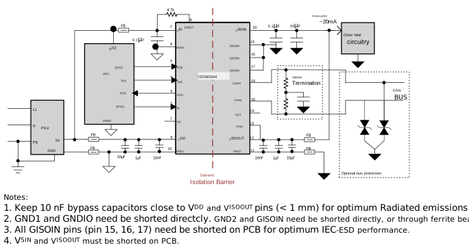 Figure 9-1 Application Circuit for
ISOW1044