SLOU432B December 2015 – December 2021 DRV2625
6 Modifying or Reprogramming the Firmware
The MSP430 firmware on the DRV2625EVM-CT can be modified or reprogrammed to create new haptic effects or behaviors. Find the latest firmware source code and binaries on ti.com. Follow the instructions below to modify or reprogram the DRV2625EVM-CT.
- Purchase one of the following MSP430F5510 compatible programmers:
- MSP430 64-pin Target Development Board and MSP-FET(MSP-FETU64USB)
- MSP-FET MCU Programmer and Debugger
- Download and install Code Compose Studio (CCS) or IAR Embedded Workbench IDE.
- Download the DRV2625EVM-CT source code and binaries from ti.com.
- Connect the programmer to an available USB port.
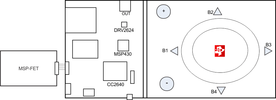
- Connect the programmer to the J6 header on the DRV2625EVM-CT.
- In CCS,
- Open the project file by selecting Project→Import Existing CCS Project.
- Select Browse and navigate to the DRV2625EVM-CT project folder, then press OK.
- Select the checkbox next to the DRV2625EVM-CT project in the Discovered projects window and then press Finish.
- Before compiling, navigate to Project→Properties→Build→MSP430 Compiler→Advanced Options→Language Options and make sure the checkbox for Enable support for GCC extensions (–gcc) is checked.
- In IAR,
- Create a new MSP430 project in IAR,
- Select the MSP430F5510 device,
- Copy the files in the project folder downloaded from ti.com to the new project directory.
Figure 6-1 below shows the connection between the MSP430 Programmer and Debugger (MSP-FET) and the DRV2625EVM-CT.
 Figure 6-1 FET Programmer Connection