SLUAAC5 August 2021 UCC28700 , UCC28701 , UCC28702 , UCC28703 , UCC28704 , UCC28710 , UCC28711 , UCC28712 , UCC28713 , UCC28720 , UCC28722 , UCC28730 , UCC28740 , UCC28742 , UCC28910 , UCC28911
- Trademarks
- 1 Introduction
- 2 Brief Review of DCM FM, AM, FM Flyback Control Law
- 3 Input (VIN) and Output (VOUT) Voltage Sensing for UVLO and OVP Fault Protection
- 4 Input Under Voltage Lockout (UVLO) Protection
- 5 Output Overvoltage (OVP) Protection
- 6 Not Recognizing a UVLO or OVP Fault
- 7 Separate Bias Supply Startup Issue and Resolution
- 8 Not Having a Clean Aux Winding Signal
- 9 Removing Aux Winding Ringing to Resolve False Triggering of OVP and UVLO Faults
- 10Noise on CS Pin Tripping Over Current Protection (OCP)
- 11Summary
- 12References
2 Brief Review of DCM FM, AM, FM Flyback Control Law
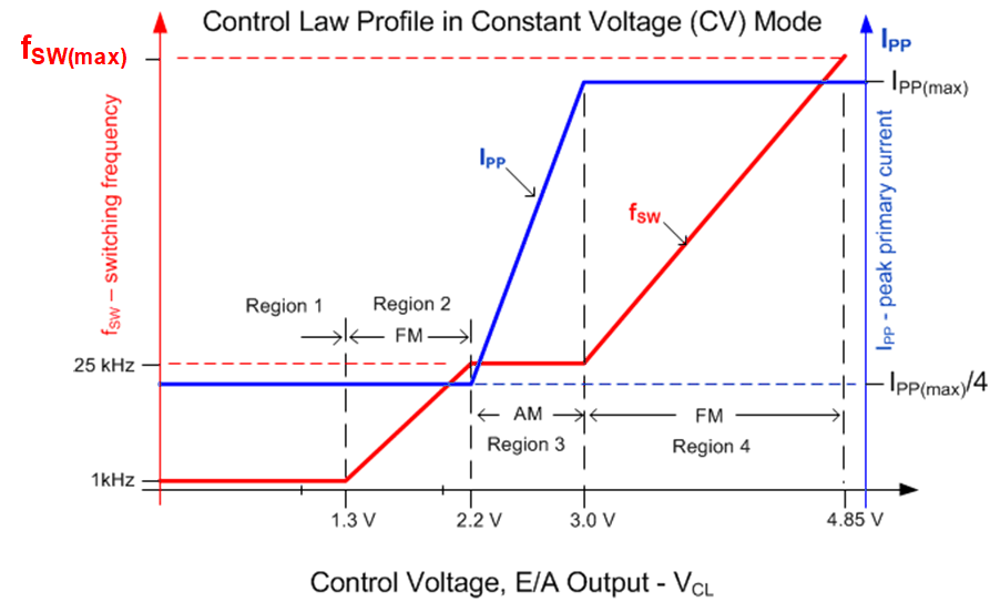
The DCM flyback controllers presented here use Frequency Modulation (FM) and Primary Peak Current Modulation (AM) to control the flyback converters frequency, duty cycle, primary peak current and output voltage. These controllers sense the output voltage at the VS pin of the flyback controller (Figure 1-1) and will adjust an internal control voltage (VCL) to adjust the primary peak current (IPP) and the converters switching frequency (fSW). This control technique is known as control law. The control law of the UCC28704 is presented in Figure 2-1. All of the devices presented in this paper use similar control laws but are parametrically different. It is required that the designer review the data sheet of the specific flyback controller they are using in their design for specific control law details.
When the converter operates at maximum load and at the minimum input voltage the application operates in critical conduction at the converter's maximum switching frequency, (fsw(max)).
When the converter operates in region 4 if less duty cycle is required, the internal feedback amplifier will adjust VCL from 4.85 V to 3.0 V to decrease fSW to obtain the correct duty cycle to maintain VOUT. The fSW will be adjusted from fSW(max) to 25 kHz minimum in region 4.
In region 3 when the converter is operating at 25 kHz, the flyback controller will adjust the primary peak current (IPP) amplitude to adjust the duty cycle. The peak current varies from the maximum programed IPP to IPP/4 to maintain the duty cycle. The device adjusts VCL from 3 V to 2.2 V in this region.
In region 2 with the primary peak current controlled to IPP/4 if the controller needs less duty cycle it decreases the switching from 25 kHz to control the duty cycle. In this region VCL operates from 2.2 V to 1.3V.
In region 1 when VCL is below 1.3 V the converter is operating at the minimum switching frequency and requires a pre-load resistor (RPL) to maintain regulation.
 Figure 2-1 Control
Law of UCC28704