SLVUBT8B November   2020  – June 2022 LP8764-Q1 , TPS6594-Q1


  1.   Scalable PMIC's GUI User’s Guide
  2.   Trademarks
  3. Introduction
  4. Supported Features
  5. Revisions
  6. Overview
  7. Getting Started
    1. 5.1 Finding the GUI
    2. 5.2 Downloading the Required Software
    3. 5.3 Launching the GUI
    4. 5.4 Connecting to a PMIC
  8. Quick-start Page
    1. 6.1 Device Scan Results
    2. 6.2 Configuration and Monitoring
      1. 6.2.1 System Info
      2. 6.2.2 BUCK
      3. 6.2.3 LDO
      4. 6.2.4 GPIO
      5. 6.2.5 Interrupts
      6. 6.2.6 Miscellaneous Settings
      7. 6.2.7 Advanced
  9. Register Map Page
  10. NVM Configuration Page
    1. 8.1 Creating a Custom Configuration
      1. 8.1.1 Static Configuration
      2. 8.1.2 Pre-Configurable Mission States (PFSM)
        1. 8.1.2.1 Creating a State Diagram
        2. 8.1.2.2 Global Settings
        3. 8.1.2.3 Power Sequence
          1. 8.1.2.3.1 Power Sequence Resources and Commands
          2. 8.1.2.3.2 Sub-sequences
          3. 8.1.2.3.3 Power Sequence Editing Tools
        4. 8.1.2.4 Trigger Settings
        5. 8.1.2.5 Trigger Priority List
        6. 8.1.2.6 PFSM Validation
    2. 8.2 Program
      1. 8.2.1 Program an Existing NVM Configuration
      2. 8.2.2 NVM Configuration Special Use Case: Changing the Communication Interface
      3. 8.2.3 Lock Option During NVM Programming
  11. NVM Validation Page
  12. 10Watchdog Page
  13. 11Additional Resources
  14. 12Appendix A: Troubleshooting
    1. 12.1 Hardware Platform Not Recognized
    2. 12.2 PMIC Device Not Found
    3. 12.3 I2C2 is configured but not connected
  15. 13Appendix B: Advanced Topics
    1. 13.1 Scripting Window
  16. 14Appendix C: Known Limitations
  17. 15Appendix D: Migration Topics
    1. 15.1 Migrating from LP8764-Q1 PG1.0 to PG2.0
    2. 15.2 Update the PFSM to Include the PFSM_START State
    3. 15.3 Update Timing Delays
    4. 15.4 Update Trigger Priority and Settings
  18. 16Revision History
Power Sequence Editing Tools

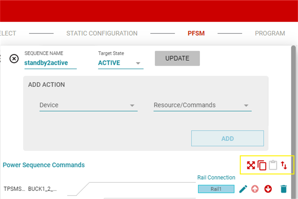
In addition to the four editing tools for each individual command (update, move up, move down, delete), there are four tools available for editing the power sequence in its entirety. From left-to-right, the tools are export power sequence, copy sequence, paste sequence, and reverse sequence (see Figure 8-21). The copy, paste, and reverse sequence tools create a convenient way to copy a power sequence, for example, a power-on sequence, and to paste in a new sequence, then reverse to create a power-off sequence.
Note: The reversal is not applied to the TRIG_MASKS as these are always intended to be at the end of the sequence. The reversal is only of the order of the commands and not the timing relationship or polarity; enable does not become disable.
GUID-20200813-CA0I-DVQN-V55W-QVPDHWS5SWQF-low.png Figure 8-21 Power Sequence Tools

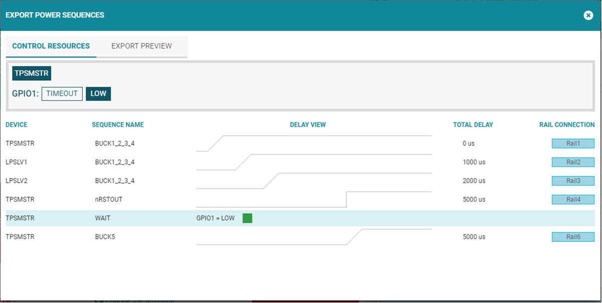
The export power sequence provides a more complete graphical view which can be exported. From this view the user has the ability to provide inputs for the conditional WAIT command and generate timing diagrams for different conditions. As shown in Figure 8-22, either the true condition of the timeout can be selected and the timing diagram is updated appropriately.
Note: Texas Instruments recommends exporting power sequences to confirm that the timing aligns with system requirements.
GUID-20200813-CA0I-D3SX-WLCN-RQKXWLWXSFPV-low.png Figure 8-22 Exported Sequence with Variable Conditions