SLVUBT8B November 2020 – June 2022 LP8764-Q1 , TPS6594-Q1
- Scalable PMIC's GUI User’s Guide
- Trademarks
- 1 Introduction
- 2 Supported Features
- 3 Revisions
- 4 Overview
- 5 Getting Started
- 6 Quick-start Page
- 7 Register Map Page
- 8 NVM Configuration Page
- 9 NVM Validation Page
- 10Watchdog Page
- 11Additional Resources
- 12Appendix A: Troubleshooting
- 13Appendix B: Advanced Topics
- 14Appendix C: Known Limitations
- 15Appendix D: Migration Topics
- 16Revision History
8.1.2.3 Power Sequence
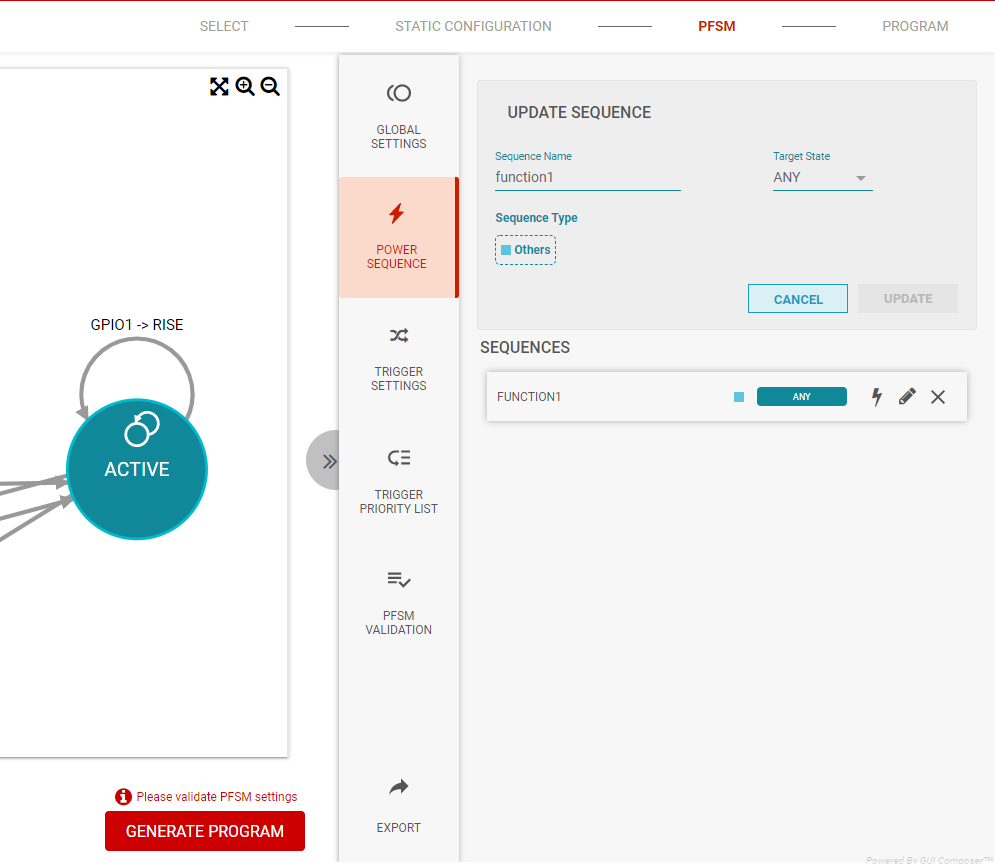
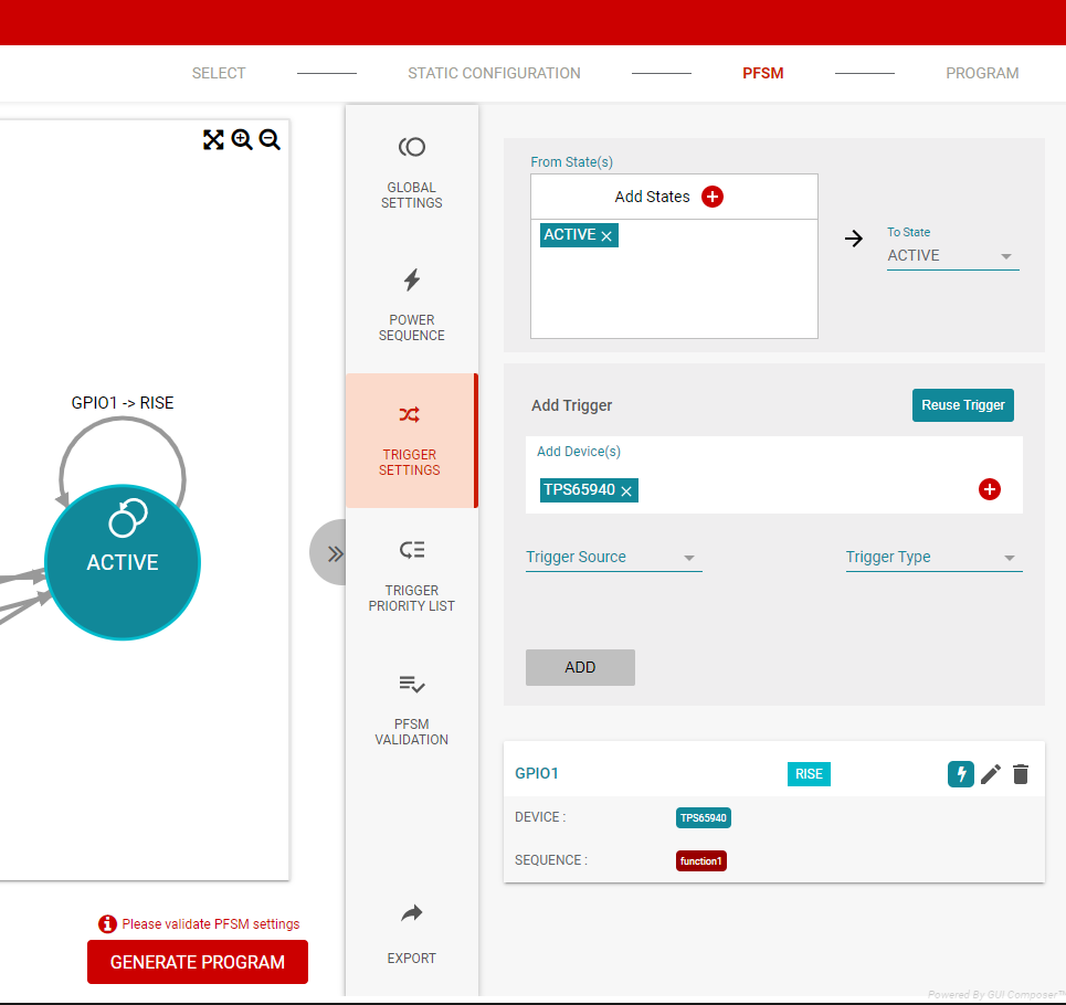
Power sequences are dependent upon the target state definition, and therefore it is required to define the state in the global settings before creating a power sequence. Most sequences apply to the transition to a specific state. Some sequences can be made target state agnostic, so that the same sequence can be reused in multiple states. These sequences require that the target state selected be 'ANY' and mapped only to transitions which are self terminating as shown in Figure 8-15 and Figure 8-16.
 Figure 8-15 Target State set to
ANY
 Figure 8-16 Self-Terminating Transition
and Trigger Association
Figure 8-16 Self-Terminating Transition
and Trigger AssociationIn addition to the target state, there are options to select the sequence type. The sequence types Power Up, Power Down, and Reset come pre-populated with ACTIVATE and or DEACTIVATE commands based upon the sequence type. The Power Down and Reset types are not recommended for use in multi-PMIC applications. Please see the DEACTIVATE descirption, 16, for a discussion on how to properly power down multiple PMICs. All sequence types have the TRIG_MASK pre-populated. These commands are described in Section 8.1.2.3.1.
The To Safe sequence type is a new means to identify which sequences lead to the SAFE_RECOVERY state. Functionally this selection has no impact, but it does alert the PFSM validation routine to inspect the sequence for required instructions before entering SAFE_RECOVERY.
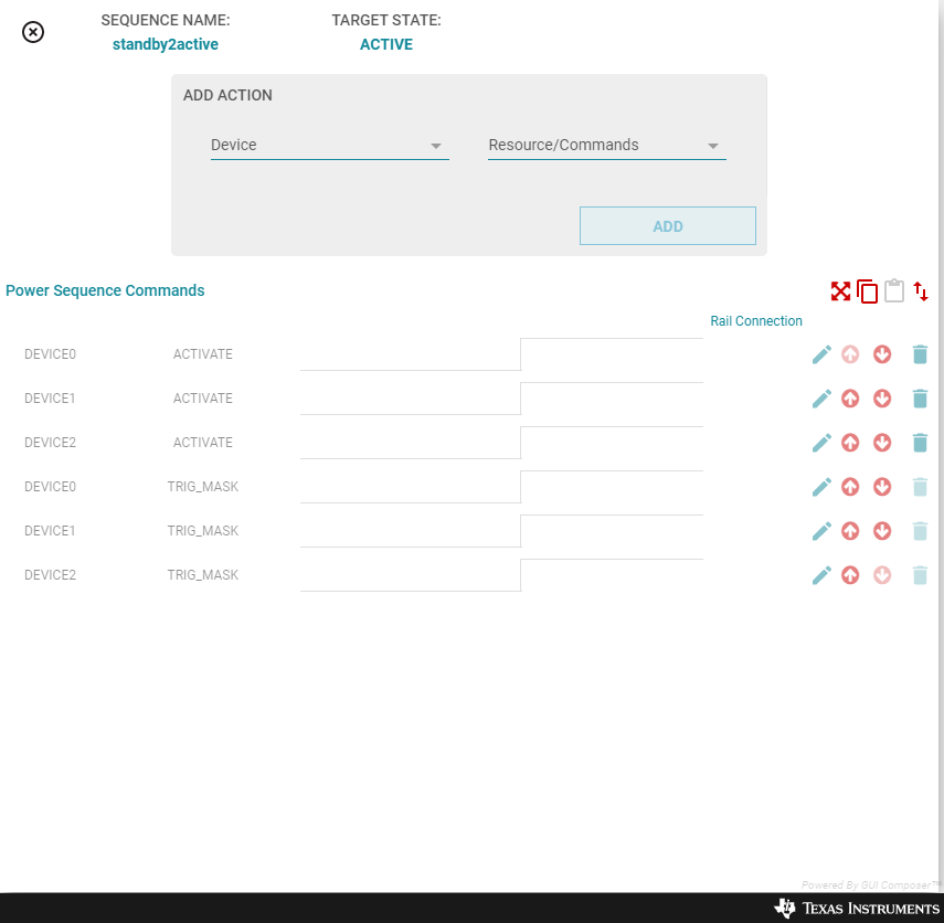
Once a new sequence has been created, then the sequence name is added to the list of sequences (see Figure 8-17), and the sequence can be edited (lightning bolt), updated (pencil), or deleted (‘X’). The update simply allows the name of the sequence to be updated as well as the target state. Using the edit icon will open a new window as shown in Figure 8-18.
 Figure 8-18 Power Sequence Command
Window
Figure 8-18 Power Sequence Command
WindowFrom this window, commands for each PMIC can be added and the timing relationship between each command is represented. Arrows are provided to move commands within the sequence.
There is a distinction between commands which have Rail Connections and commands which do not. The commands with Rail Connections are typically representative of physical outputs from the device and voltage monitors. The Rail Connections are what will appear in the power sequence diagram as described in section Section 8.1.2.3.3. The names of the Rail Connections are editable and can be updated to more meaningful names related to the application.
Initially, the trigger masks for each device are provided. As additional commands are added, they will always be placed above the trigger masks. The trigger masks can be moved in the sequence order, but typically these are the last commands in the sequence. The trigger mask at the end of the power sequence is automatically generated based upon the available triggers of the destination state. This mask can be edited to mask triggers from triggering a power sequence and a state change. Before editing the mask. it is recommended to define the triggers as described in the Section 8.1.2.4.