SLYA048B March 2020 – June 2021 FDC1004 , FDC1004-Q1 , FDC2112 , FDC2112-Q1 , FDC2114 , FDC2114-Q1 , FDC2212 , FDC2212-Q1 , FDC2214 , FDC2214-Q1 , LDC0851 , LDC1001 , LDC1041 , LDC1051 , LDC1101 , LDC1312 , LDC1312-Q1 , LDC1314 , LDC1314-Q1 , LDC1612 , LDC1612-Q1 , LDC1614 , LDC1614-Q1 , LDC2112 , LDC2114 , LDC3114 , LDC3114-Q1
- Trademarks
- 1Inductive and Capacitive Theory of Operation
- 2FDC: Capacitive Level Sensing
- 3LDC: Inductive Touch Buttons
- 4LDC: Incremental Encoder and Event Counting
- 5LDC: Metal Proximity Sensor
- 6Revision History
1.1 Inductive Sensing Theory of Operation
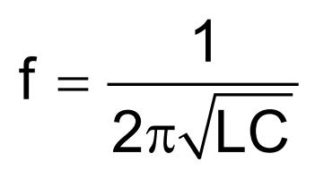
LDC devices operate on a resonant sensing principle. The sensor connected to the LDC is essentially a fixed capacitor in parallel with an inductor, which is typically a coil printed on a PCB as shown in Figure 1-1.
 Figure 1-1 LDC Theory of Operation
The fixed capacitor and inductive coil form the external LC tank circuit required for LDC operation. Use Equation 1 to calculate the inherent resonant frequency of this LC tank.
As a conductive target approaches the inductive coil, eddy currents form on the surface of the conductive target. The magnetic field of these eddy currents resist the current of the inductive coil, which reduces the inductance of the system and increases the resonant sensing frequency. The LDC devices convert this resonant sensing frequency to a digital value for the user to see. The frequency shift upon a metal target is shown in Figure 1-2.
 Figure 1-2 Resonant Frequency Shift in Presence of Metal
For a more detailed explanation of the LDC theory of operation, along with the differences between the LDC devices, see the LDC Device Selection Guide.