SLYY081B March 2018 – January 2024 AMC1305M25 , AMC1311 , AMC1311-Q1 , ISO1042 , ISO1042-Q1 , ISO5851 , ISO7741 , ISO7841 , ISOM8710 , UCC20225-Q1 , UCC20225A-Q1 , UCC21520 , UCC21540 , UCC23513 , UCC5390
Failure mode 2: A combination of high voltage and high current close to the isolation barrier
Under abnormal or fault events, it is possible that the voltage or currents on one side of the isolator can be very high with respect to the ground on the same side (see Figure 5). One example of this is a short circuit event on a low-impedance output pin. Another example is a short circuit of any pin to a high-voltage DC bus line resulting in electrical breakdown. These are high-power events since high voltages and high currents are simultaneously present.
 Figure 5 High-power dissipation on one
side of the isolator.
Figure 5 High-power dissipation on one
side of the isolator.When these events occur, electrical over stress (EOS) or internal heating can cause the isolation barrier to degrade. For example, if the optocoupler in Figure 6 has a high power event on side 2, it can cause heating or EOS on the detector die. This damage can easily extend into the insulation material, which can degrade isolation performance. It is fair to assume that the insulation is not completely destroyed, but at the same time it is difficult to quantify exactly how much insulation is left.
 Figure 6 High-power dissipation on one
side of the isolator.
Figure 6 High-power dissipation on one
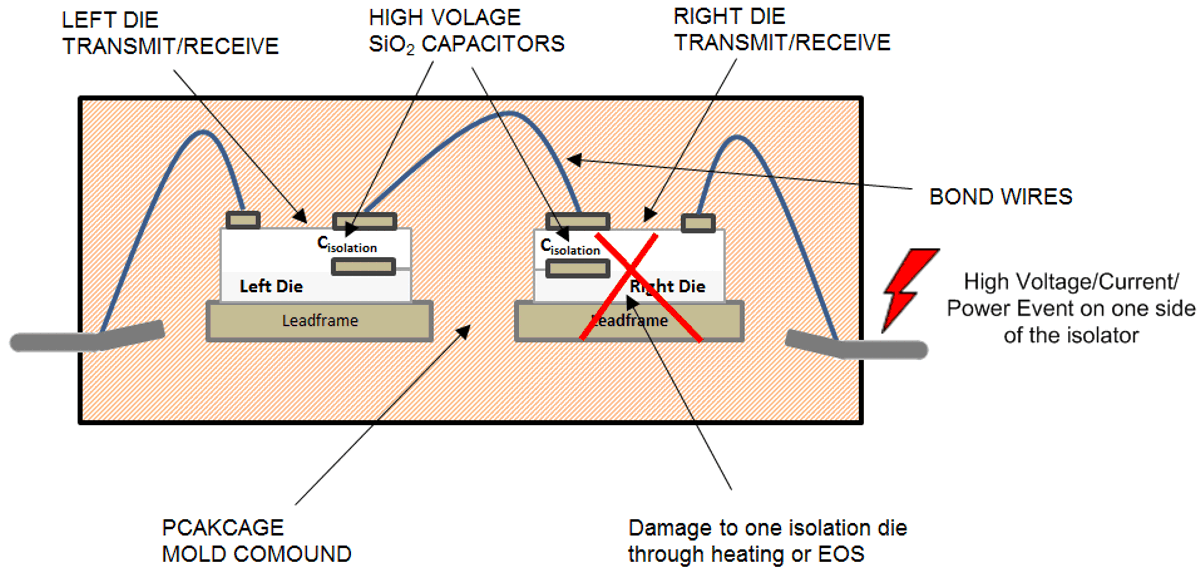
side of the isolator.Looking at Figure 7 for a series capacitor-based isolator, a high-voltage/high-power event on side 2 could damage the right die, and along with it the isolation capacitor that is part of the right die. However, due to the interceding mold compound, the damage does not extend to the left die nor to the isolation capacitor placed on that die. This maintains isolation while preserving roughly half of the original insulation. For instance, if the original isolator is rated for reinforced isolation, after the high-power event, it can be expected to retain full isolation rating of one capacitor. Therefore, while the isolator “fails open,” the “basic insulation” is still maintained.
 Figure 7 High-power dissipation on one
side of the isolator.
Figure 7 High-power dissipation on one
side of the isolator.One way to prevent failure mode 2 is to ensure through external means, for example through current limited power supplies, that even under fault events the heat dissipated inside the isolator is limited to a certain safe limit. This limit is specified through “safety limiting values” for current and power in isolator data sheets, below which the isolation performance remains intact.
However, such current limits are not always feasible to implement. Going back to Figure 1, if the IGBT (1) suffers from a collector to gate breakdown, the high voltage of the DC bus appears at the gate-driver output pin and causes electrical overstress on circuitry connected to that pin. There is no easy way to prevent this from happening at the system level. In such scenarios, the “fail open” behavior of
TI reinforced isolators greatly enhances the system’s electrical safety.