SLYY200A April 2021 – December 2023 LM25149 , LM25149-Q1 , LM5156-Q1 , LM5157-Q1 , LM53635-Q1 , LM60440-Q1 , LM61460-Q1 , LM61495-Q1 , LMQ62440-Q1 , LMR33630-Q1 , LMS3655-Q1 , TPS55165-Q1 , UCC12040 , UCC12050
- 1
- Overview
- At a glance
- What is EMI?
- Conventional methods to reduce EMI in the low- and high-frequency ranges
- Innovations in reducing low-frequency emissions
- Spread spectrum
- Active EMI filtering
- Cancellation windings
- Innovations in reducing high-frequency emissions
- HotRod™ package
- Enhanced HotRod QFN
- Integrated input bypass capacitor
- True slew-rate control
- EMI modeling capabilities
- Low-frequency EMI designs using WEBENCH® design tool
- Conducted and radiated EMI results published in data sheets
- Conclusion
- Keep product categories for low EMI
Spread spectrum
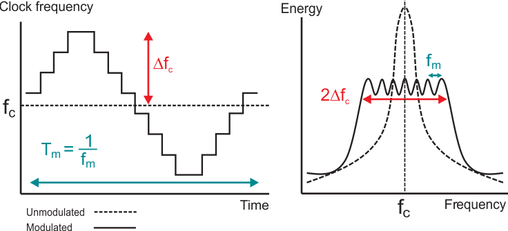
Spread spectrum uses the principle of conservation of energy to reduce EMI peaks by spreading energy across multiple frequencies. However, the peak energy that a susceptible circuit “sees” may not reduce; it depends on the relationship between the susceptible circuit’s bandwidth and the method of frequency modulation. When measuring EMI, the spectrum analyzer is acting as the susceptible circuit, and industry standards set the resolution bandwidth (RBW). Thus, it is important to modulate the frequency in the most effective way for the standard you are targeting. A general rule of thumb is to have the modulation frequency, fm, approximately equal to your targeted RBW, with the spreading bandwidth, ΔfC, around ±5% to ±10%. Figure 9 illustrates these parameters in both the time and frequency domains.
 Figure 9 Spread-spectrum parameters
fm and ΔfC in both the time and frequency
domains.
Figure 9 Spread-spectrum parameters
fm and ΔfC in both the time and frequency
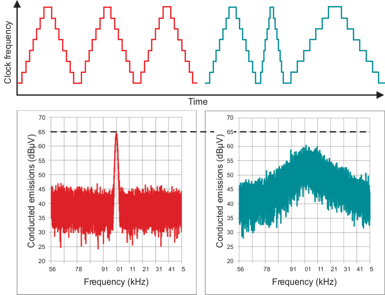
domains.It is common to set fm around 9 kHz to optimize for the low-frequency band in standards such as CISPR 25, but this happens to also be in the audible range. To combat this, you can further modulate the triangular modulation in a pseudo random fashion to spread the audible energy without having a significant impact on the conducted and radiated EMI performance. Figure 10 illustrates this modulation profile both in the time and the frequency domains, a feature present on the TPS55165-Q1, a synchronous buck-boost converter.
 Figure 10 Audible tone reduction
achieved by pseudo randomly modulating the triangle waveform at the conclusion
of every modulation cycle.
Figure 10 Audible tone reduction
achieved by pseudo randomly modulating the triangle waveform at the conclusion
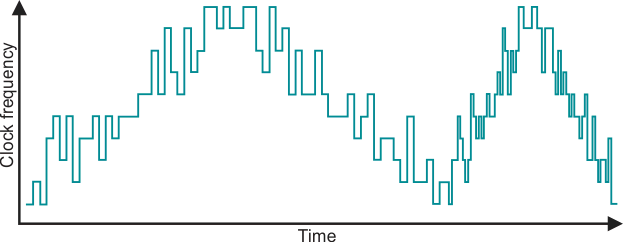
of every modulation cycle.The fact that EMI is not limited to a single band (and thus a single RBW) but multiple bands presents a predicament, as spread spectrum can typically only target improvements in a single band. A new solution to this problem is a digital spread-spectrum technique called dual random spread spectrum (DRSS). The basic principle behind DRSS is to superimpose two modulation profiles, each targeting a different RBW. For more information, see the application report, EMI Reduction Technique, Dual Random Spread Spectrum. Figure 11 shows a DRSS modulation profile in the time domain, with a triangular envelope targeting lower RBWs, and a superimposed pseudo random sequence targeting higher RBWs.
 Figure 11 Time domain modulation profile
of DRSS.
Figure 11 Time domain modulation profile
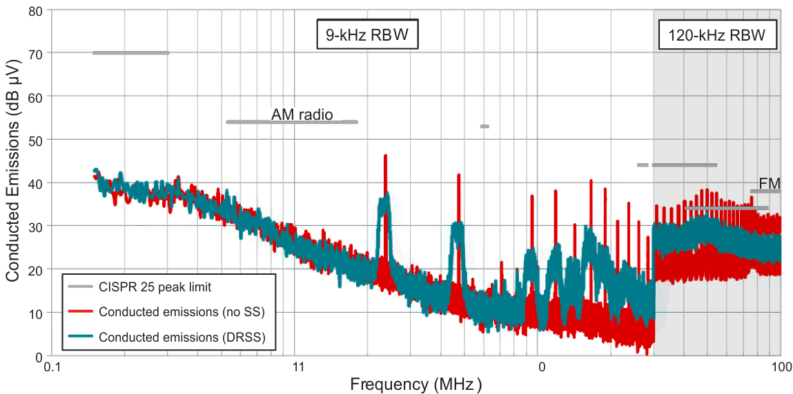
of DRSS.Figure 12 shows the conducted emissions performance of the LM5156-Q1, a non-synchronous boost controller, with and without DRSS. You can see significantly reduced spectral peaks in both the 150-kHz to 30-MHz band, as well as the 30- to 108-MHz band, which are the two key bands for the CISPR 25 automotive standard. The LM5157-Q1 non-synchronous boost converter also features DRSS and achieves similar performance.
 Figure 12 EMI performance of the
LM5156-Q1 boost controller before and after spread spectrum, using a printed
circuit board (PCB) not specifically designed for lower EMI.
Figure 12 EMI performance of the
LM5156-Q1 boost controller before and after spread spectrum, using a printed
circuit board (PCB) not specifically designed for lower EMI.Spread-spectrum techniques are applicable for both non-isolated and isolated topologies, as the EMI sources are similar for both, and frequency spreading provides the same benefit. The UCC12040 and UCC12050 isolated DC/DC converters with integrated transformers are able to pass CISPR 32 Class B EMI testing limits in part due to internal spread-spectrum techniques.