SNLA356 September 2020 DS90UB941AS-Q1 , DS90UH941AS-Q1
4.2 Missing Periodic Low Power Transitions
A common cause for failure to receive video during end to end bring-up with DS90UB941AS-Q1 is due to DSI source configuration for BLLP behavior. As described in section 1.3, a DSI source is required by the DSI v1.3.1 specification to periodically enter LP11 (Low Power Mode) on the data lanes (not the clock) at least once per frame. Some common DSI driver examples in the market do not enable LP11 mode by default during any of BLLP periods in the video stream. This will result in the DS90UB941AS-Q1 not initializing the DSI receiver to start forwarding video through the FPD-Link output*.
Symptoms:
- Black screen
- DSI clock is detected and the FPD-Link is running at-speed according to the desired video rate but there is no video data present at the deserializer
- No data type is reported by the DS90UB941AS-Q1 in the DSI_VC_DTYPE register
How to Verify:
Verify the detected DSI pixel frequency by reading the DSI_FREQ register 0x5F via I2C. In this system state, the DSI pixel frequency should match expectations based on the video rate and should not report 0MHz.
- Check the DSI_VC_DTYPE register via
I2C:
- Write 0x40 = 0x04 for DSI Port 0 or 0x40 = 0x08 for DSI Port 1
- Write 0x41 = 0x2A
- Read 0x42 (DSI_VC_DTYPE)
- The DSI_DTYPE is contained in bits 5:0
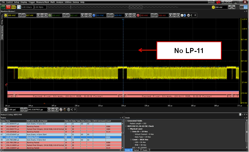
To verify that LP-11 is being entered periodically by the DSI source, the system designer can probe one of the active DSI data lanes during video transmission. This can be done with a single ended probe attached between one of the data lane P/N nets and GND. The goal is to set the oscilloscope trigger to capture the LPTX signal amplitude only, while ignoring the HS data transmission.
During HS mode transmission, each data lane is expected to have a common mode voltage between 150-250mVm and a differential swing of 140-270mV.
During Low Power Mode (LP-11), the P/N data lanes will no longer be differential. They will both transition to the LPTX high level output voltage of 0.95-1.3V.
Set the oscilloscope trigger level to 800mV and monitor the data lane activity. If the DSI source is properly configured to output periodic LP-11 pulses, then the scope should trigger at least once per frame. The period of the frame is defined by the video refresh rate - commonly 16.6ms for 60Hz refresh. If the scope does not trigger from the 800mV level, then the DSI source driver has not been properly configured.
Example:
 Figure 4-1 Example DSI Data Lane With No
Periodic Low Power States
Figure 4-1 Example DSI Data Lane With No
Periodic Low Power StatesResolution:
The DSI source driver must be configured to enter Low Power Mode (LP-11) at least once per frame during one of the available BLLP periods. Consult the kernel driver manual for the DSI source for options to enable periodic Low Power Mode. Some examples of flags in the DSI source driver pertaining to this configuration are:
- mdss-dsi-bllp-eof-power-mode
- mdss-dsi-bllp-power-mode