SNLA415 August 2022 DS160PT801
6.2 Phase 2 and 3
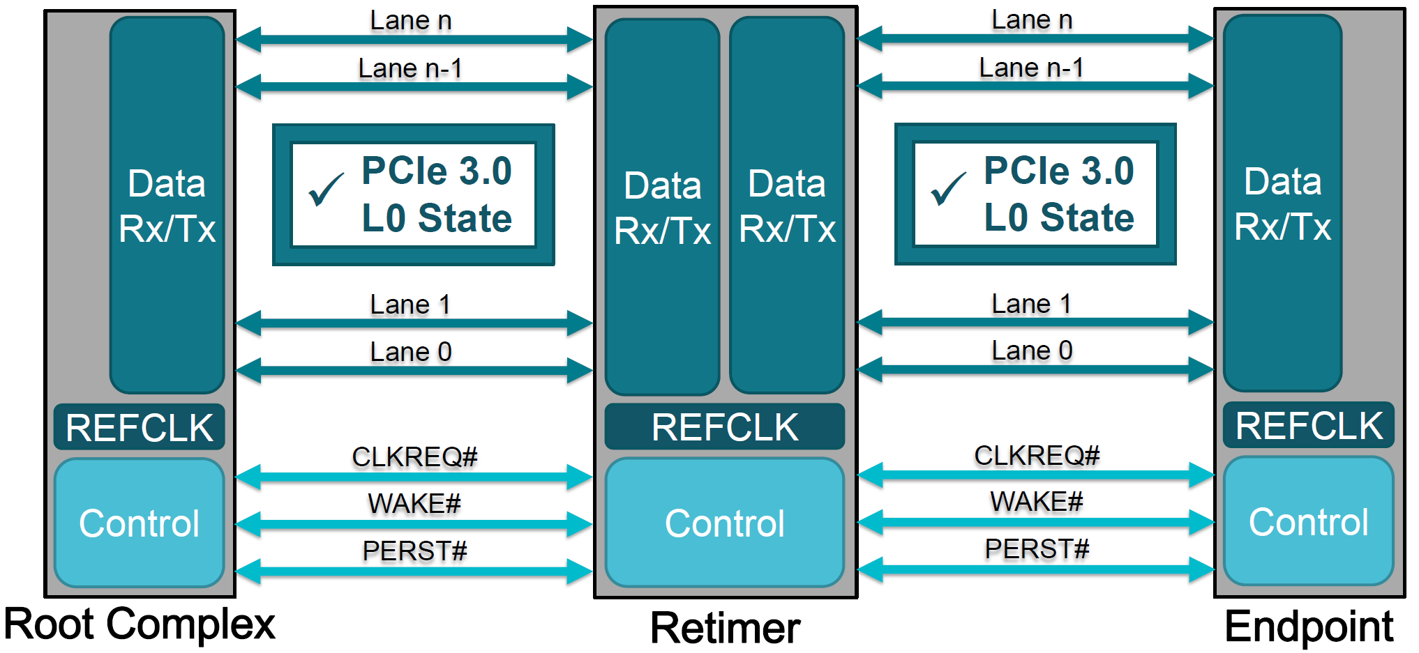
In phase 2 and 3, link equalization conducts fine tuning on the link. This further optimizes the preset values for the upstream port. Then, in phase 3, same optimization happens for the downstream ports. After completing Phase 3 of the link equalization process, link equalization is completed, and the PCIe link should have BER less than 10-12. In some motherboard designs, particularly those with long channel links, this level of signal quality is not possible. Additional signal conditioning may be required. In this case, repeaters like redrivers and retimers are used to conduct signal conditioning and provide high-quality signal between the endpoints and the root complex. The link now moves into L0 state in Gen 3 and can communicate reliably at that speed. Figure 6-3 shows the diagram of PCIe devices connected in PCIe Gen 3 data rate after link equalization that started with Gen 1 connection. For connection at higher data rate, PCIe devices have to go through more link equalization processes.
 Figure 6-3 L0 State of PCIe Devices After
Link Equalization