SNLU226B February 2018 – April 2021 DS90UB960-Q1
- 1 Introduction
- 2 Features
- 3 Application Diagram
- 4 Major Components
- 5 Quick Start Guide
- 6 Board Connections
- 7 Enable and Reset
- 8 ALP Software Setup
- 9 Troubleshooting ALP Software
- 10Typical Connection and Test Equipment
- 11Termination Device
- 12Typical Test Setup
- 13Equipment References
- 14Cable References
- 15Bill of Materials
- 16PCB Schematics
- 17Board Layout
- 18Revision History
8.4 Startup - Software Description
Make sure all the software has been installed and the hardware is powered on and connected to the PC. Execute “Analog LaunchPAD” shortcut from the start menu. The default start menu location is under All Programs > Texas Instruments > Analog LaunchPAD vx.x.x > Analog LaunchPAD to start MainGUI.exe.
 Figure 8-1 Launching ALP
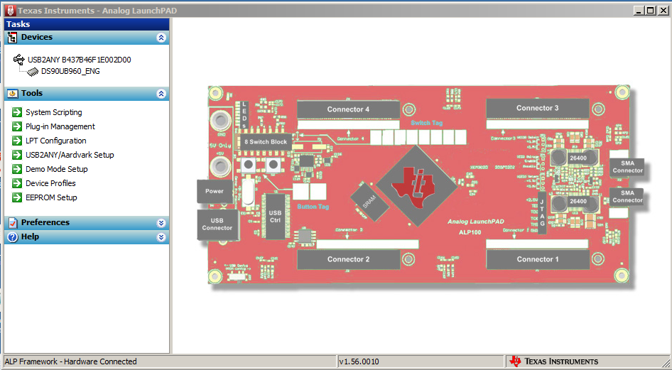
The application must come up in the state shown in Figure 8-2. If it does not, see Section 9, “Troubleshooting ALP Software”.
Under the Devices tab click on “DS90UB960” or "DS90UB960_ENG" to select the device and open up the device profile and its associated tabs.
 Figure 8-2 Initial ALP Screen
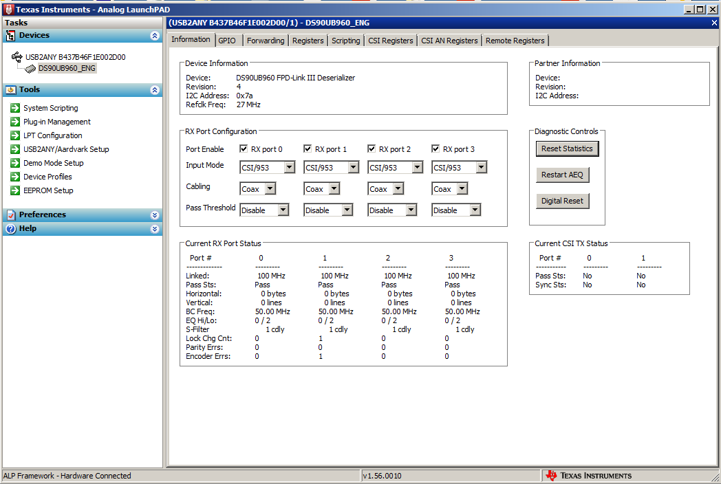
After selecting the “DS90UB960” or "DS90UB960_ENG", the following screen shown in Figure 8-3 must appear provided four camera modules with DS90UB953-Q1 are connected to the EVM.
 Figure 8-3 Follow-up Screen