SNOA930C March 2015 – May 2021 LDC0851 , LDC1001 , LDC1001-Q1 , LDC1041 , LDC1051 , LDC1101 , LDC1312 , LDC1312-Q1 , LDC1314 , LDC1314-Q1 , LDC1612 , LDC1612-Q1 , LDC1614 , LDC1614-Q1 , LDC2112 , LDC2114 , LDC3114 , LDC3114-Q1
2.3 Multiple Layers
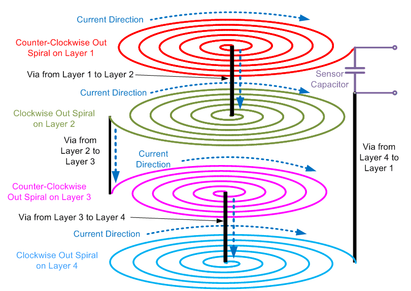
For PCB inductors, there is a maximum number of turns that can be placed in a given diameter. If the overall inductance of the sensor is still too low, adding an additional inductor on another layer increases the total inductance. Note that these additional inductors need to be physically aligned, as shown in Figure 2-6, so that the magnetic fields positively add. Electrically, the inductors are connected in series. In general, with a PCB spiral inductor, a second layer is generally available because most PCBs are at least two layers.
When routing multiple layers, it is important to alternate the rotation of the coils – if the top layer is routed with a clockwise rotation, the next layer down must have a counter-clockwise rotation. While this may seem counter-intuitive, this physical arrangement is needed in order to keep the current rotating in a constant direction.
 Figure 2-6 Multiple Layer Inductor Construction (Series)
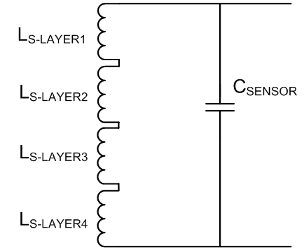
 Figure 2-7 Simplified Electrical Model of Four-Layer Series Sensor (Ignoring RP)