SNOA930C March 2015 – May 2021 LDC0851 , LDC1001 , LDC1001-Q1 , LDC1041 , LDC1051 , LDC1101 , LDC1312 , LDC1312-Q1 , LDC1314 , LDC1314-Q1 , LDC1612 , LDC1612-Q1 , LDC1614 , LDC1614-Q1 , LDC2112 , LDC2114 , LDC3114 , LDC3114-Q1
2.4 Inductor Size
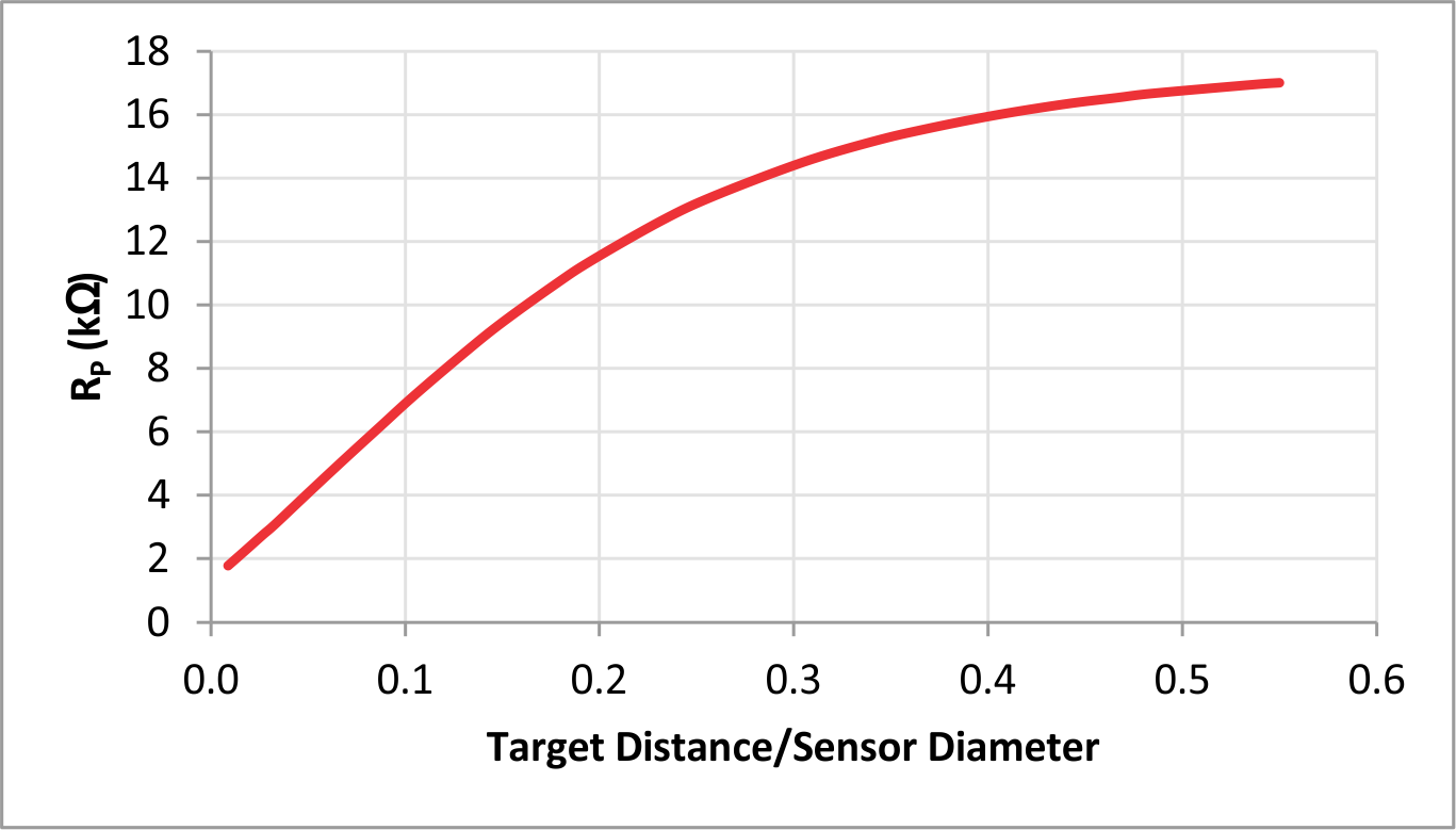
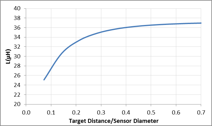
The primary inductor characteristic that determines sensing range is the physical size of the inductor. More specifically, the outer diameter (dOUT) determines the sensing range. In order to sense the movement of a target, the magnetic field of the sensor needs to extend to the target. The physical size of the inductor controls the physical size of the generated magnetic field. The change in sensor inductance as a function of the target distance has a consistent shape, as seen in Figure 2-11 and Figure 2-12. The change in inductance versus the change in target distance has such a consistent shape that users can effectively scale the response to the sensor diameter (dOUT) to simplify system design.
It may be surprising to learn that the overall inductance of the sensor, which corresponds to the intensity of the magnetic field, does not significantly affect the sensing range.
Figure 2-11 and Figure 2-12 show the transfer functions of an example 14-mm diameter sensor. While a different inductor geometry has a different scale on the Y-axis on the graphs, the overall shape is similar as the target is proportionally moved. As the distance between the sensor and target decreases, both L and RP decrease. The amount of the decrease is based on the target size and composition, although for some target materials the L and RP can actually increase as the target gets closer. It must be noted that in the sensor/target scenario, the flux linkage between the sensor and target does not add, but instead, the fields oppose one another, so that the mutual inductance between the two has on a negative sign.
 Figure 2-11 RP Versus Normalized Target Distance
 Figure 2-12 Inductance Versus Normalized Target Distance
For LDC131x and LDC100x devices, the effective sensing range is approximately one-half the sensor diameter. While the L versus distance response is the same for LDC161x devices, the higher resolution of the LDC161x enables it to effectively sense target shifts at much larger distances – up to twice the sensor diameter, but with reduced effective measurement resolution. The LDC211x and LDC3114 devices have an equivalent sensing range to the LDC161x. For the LDC0851, the maximum switching distance is 40% of the coil diameter.
If a system requires a sensing range of 4 mm, then the minimum sensor size must be 8 mm; and an even larger sensor provides improved measurement resolution. This leads to the first rule of thumb for inductive sensor design: use the biggest coil that can physically fit in the application. The second rule of thumb for inductive sensor design is that the target must be similar in size to the sensor.
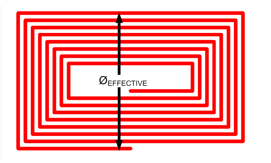
When using rectangular inductors or other non-circular shapes, the sensing range is based on the smaller axis rather than the longer axis, as shown in Figure 2-13.
 Figure 2-13 Sensor “Diameter” for a Non-circular Coil