SPRACN1 May 2019 TMS320F2800132 , TMS320F2800133 , TMS320F2800135 , TMS320F2800137 , TMS320F2800152-Q1 , TMS320F2800153-Q1 , TMS320F2800154-Q1 , TMS320F2800155 , TMS320F2800155-Q1 , TMS320F2800156-Q1 , TMS320F2800157 , TMS320F2800157-Q1 , TMS320F280021 , TMS320F280021-Q1 , TMS320F280023 , TMS320F280023-Q1 , TMS320F280023C , TMS320F280025 , TMS320F280025-Q1 , TMS320F280025C , TMS320F280025C-Q1 , TMS320F280040-Q1 , TMS320F280040C-Q1 , TMS320F280041 , TMS320F280041-Q1 , TMS320F280041C , TMS320F280041C-Q1 , TMS320F280045 , TMS320F280048-Q1 , TMS320F280048C-Q1 , TMS320F280049 , TMS320F280049-Q1 , TMS320F280049C , TMS320F280049C-Q1
3 Hardware Modifications
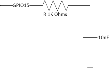
Once the above settings are programmed into the OTP, GPIO15 is selected as the boot select pin with a low value (0) on the pin selecting Flash boot mode and a high value (1) on the pin selecting SCI boot mode. A resistor and a capacitor need to be connected between GPIO15 and ground to enable software control of the boot mode, as and when needed by the application. The resistor rating needed is derived to be 1KΩ and the capacitor rating is derived to be 10 nF. These values are derived considering the worst case leakage current of 2 µA and other device characteristics defined in the TMS320F28004x Piccolo™ Microcontrollers Data Manual.
 Figure 1. Hardware Connections