SPRACP7 October 2019 AM6526 , AM6528 , AM6546 , AM6548
3.1 AM65xx as the Time Master Server
In this scenario, the AM65xx device receives two master PPS signals from its timer input pins. These pins can be driven by external GPS receivers, a trusted clock source, or other types of master time-base generation units. These PPS signals are captured by NAV-CPTS module, and corresponding IEP timers are tuned to follow these master time-bases, then PTP packets are transmitted to downstream network components via IEEE 802.1AS protocol.
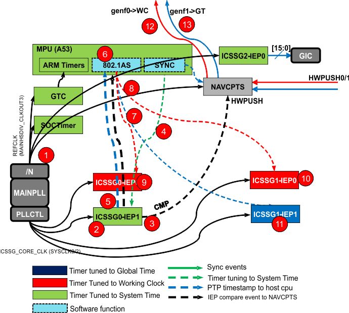
Figure 8 shows related clock signals and dotted lines represent software adjustment functions. In this scenario, the device maintains three time bases: system time, wall clock, and working clock.
 Figure 8. Time-Sync Use Case Example 1: AM65xx as Time Masters
 The programming steps are as follows:
- Configure GTC, DM Timers, NAV-CPTS, ICSSG2 all use REFCLK from MAINHSDIV_CLKOUT3. This time-base is selected as System Time.
- Configure ICSSG0/1 to work in Sync mode, configure all IEPs in ICSSG0/1 to use the core_clk as IEP clock, running at 250 MHz.
- Configure ICSSG0-IEP1 to generate a SYNC event, configure the event to HWPUSH of NAVCPTS.
- The SYNC software stamps HWPUSH and calculate offset between ICSSG core clock and system time. Then, tune ICSSG0-IEP1 to System time.
- ICSSG0 use IEP1 to timestamp Global Time and Working Clock PTP, give timestamps to the 802.1AS modules on host processor.
- 802.1AS stack calculate actual working clock, and also
- ∆wc: clock offset between Working Clock and System Time
- ∆gt: clock offset between Global Time and System Time
- ICSSG1-IEP1 is tuned to Global Time and used by TSN software to send out wall clock.
- ICSSG0/1-IEP0 is tuned to Working Clock and used by TSN software to send out Working Clock.
- Working clock is sent out by ICSSG0 for ProfiNet.
- Working clock is sent out by ICSSG1 for TSN.
- Global time is sent out by ICSSG1 to TSN based on ICSSG1-IEP1.
- SYNC software configures NAV-CPTS GENF0 to send out test sync for the Working Clock.
- SYNC software configures NAV-CPTS GEN1 and sends out the test Sync for GT. GENF1 need to be tuned to Global Time.