SPRACT7 August 2020 TMS320F280021 , TMS320F280021-Q1 , TMS320F280023 , TMS320F280023-Q1 , TMS320F280023C , TMS320F280025 , TMS320F280025-Q1 , TMS320F280025C , TMS320F280025C-Q1 , TMS320F280040-Q1 , TMS320F280040C-Q1 , TMS320F280041 , TMS320F280041-Q1 , TMS320F280041C , TMS320F280041C-Q1 , TMS320F280045 , TMS320F280048-Q1 , TMS320F280048C-Q1 , TMS320F280049 , TMS320F280049-Q1 , TMS320F280049C , TMS320F280049C-Q1
2.2 Current Sensing Technique
Fast and precise current sensing is required in motor control applications to have the minimum torque ripple and thus minimum audible noise. Accurate current sensing is important to have the best dynamic motor control. The delay in current sensing path can leads to incorrect current estimates and hence distorted current waveform in motor. The motor drive applications in major appliances such as a compressor motor control in air conditioners and refrigerators require accurate torque control to have best dynamic performance and lower acoustics. An inaccurate current sensing lead to distorted current waveform in the motor winding and thus produces torque ripple, which, in turn, results in inefficient and noisy performance.
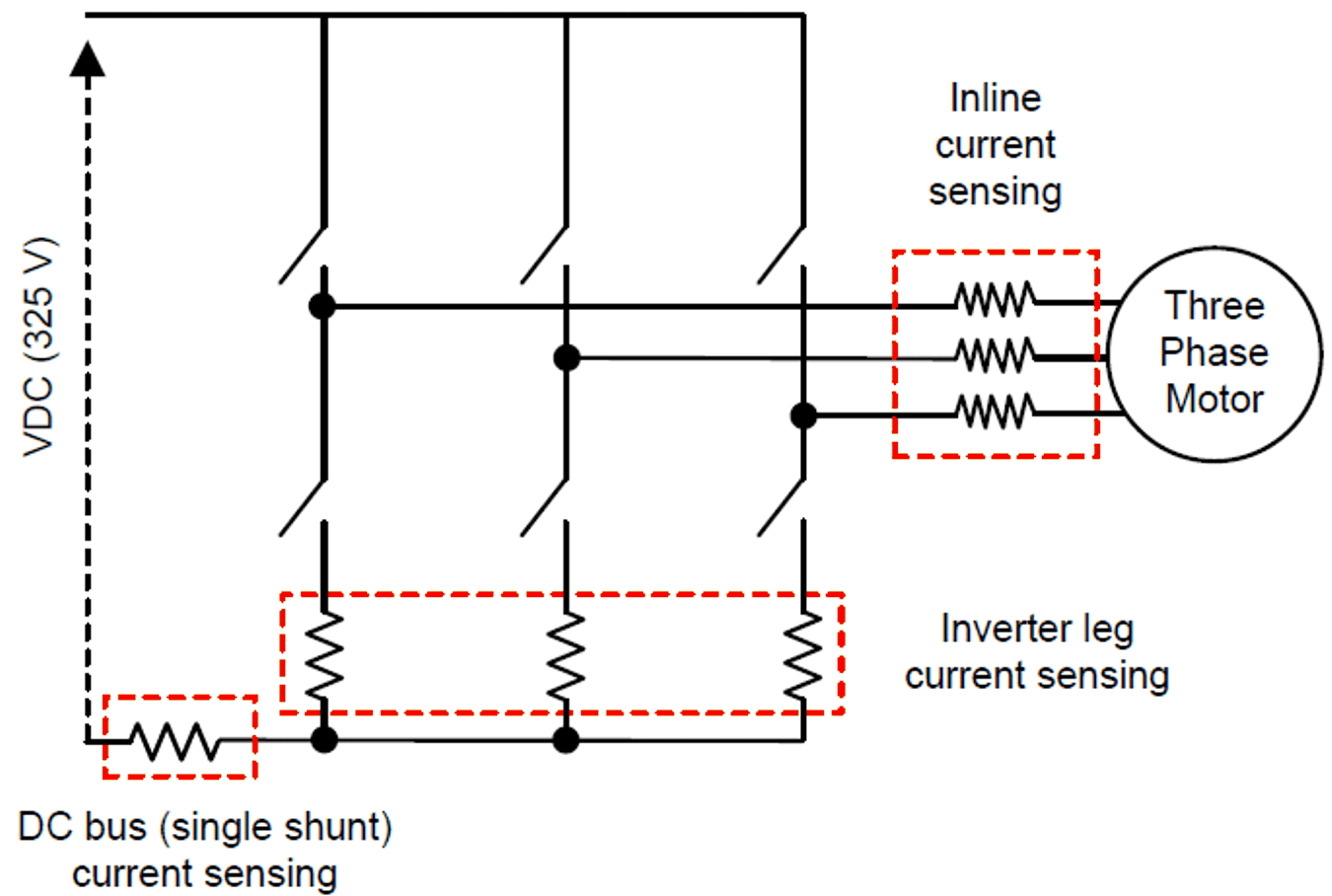
Control the inverter system requires knowing the motor current information. For a three phase motor, the designer must know all the phase currents to be able to control the motor torque. The motor- phase winding current can be sensed by using different methods, for which the commonly- used methods are:
- Inline current sensing
- Inverter leg current sensing
- DC bus current sensing using a single-shunt
Figure 2-2 shows the placement of current sensor in the previously mentioned sensing methods.
 Figure 2-2 Different Current Sensing Method
Used in Three-Phase Inverter
Figure 2-2 Different Current Sensing Method
Used in Three-Phase InverterThe simplest method of obtaining motor winding current is by measuring each of phase current directly at the phase node by placing a current sensor in line with the phase connection. Depending on the motor winding connections, this measurement requires at least two sensors to be applied directly to the individual motor phases. The common mode voltage existing in the inline sensing is equal to the DC bus voltage, which makes non-isolated shunt based sensing difficult. Isolated sensors are normally used in these lines and are usually sophisticated and expensive. Use of a non-isolated shunt-based solution is preferred in applications where the common-mode voltage is typically less than 100 V.
Another method is to measure the inverter leg currents as Figure 2-2. In this case, the common-mode voltage is close to zero and a low-cost shunt and an operational amplifier (op amp) can be used to sense the inverter current. The current sampling has to be done when the low-side switch is ON and the current sampling point must be synchronized with the pulse-width modulation (PWM). The ideal method is to use three-leg inverter current sensing. Two-leg inverter current sensing must be performed at the minimum to obtain accurate information on each of the three winding currents.
Another method, which is more complex, is to measure only the DC line current and then identify each of the three-phase currents sequentially in the different inverter switching states. Because the switching state of the inverter is controlled by the micro controller unit (MCU) or digital signal processor (DSP), the designer can determine the exact electrical route taken by the input current through the inverter, which allows the designer to directly relate the DC bus current to the motor phase current. The obtained phase currents are the result of a real measurement of the current and are not the result of an estimation that requires a model of the circuit. This method is broadly being used in the home appliance and automotive applications because of BOM cost saving.
Section 2.2.1 provides a detailed analysis of the different low side current sensing performed.