SPRACX7 April 2021 AWR1243 , AWR1443 , AWR1642 , AWR1843 , AWR1843AOP , AWR2243 , AWR2944 , AWR6843 , AWR6843AOP , IWR1443 , IWR1642 , IWR1843 , IWR6443 , IWR6843 , IWR6843AOP
2 Low-Cost Manufacturing Setup
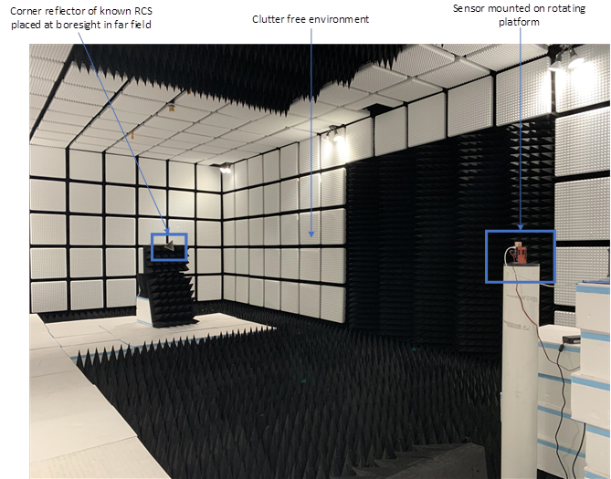
When testing any RF parameters or performing calibrations, it is important to ensure that the tests are performed in a clutter free environment. Ideally, tests should be done in an anechoic chamber to minimize clutter and ensure that the corner reflector is easily identifiable. However, as long as the noise created by the clutter is low enough so that there is no chance for a competing object to be used for calibration, an anechoic chamber is not necessarily required. In the event that an environmental object is accidentally used in calibration, this could cause the sensor to malfunction and underperform in the field. This section describes the typical hardware needed for a radar production test environment.
 Figure 2-1 Example Test Environment