SPRUJ29A April 2022 – January 2023
1 Introduction
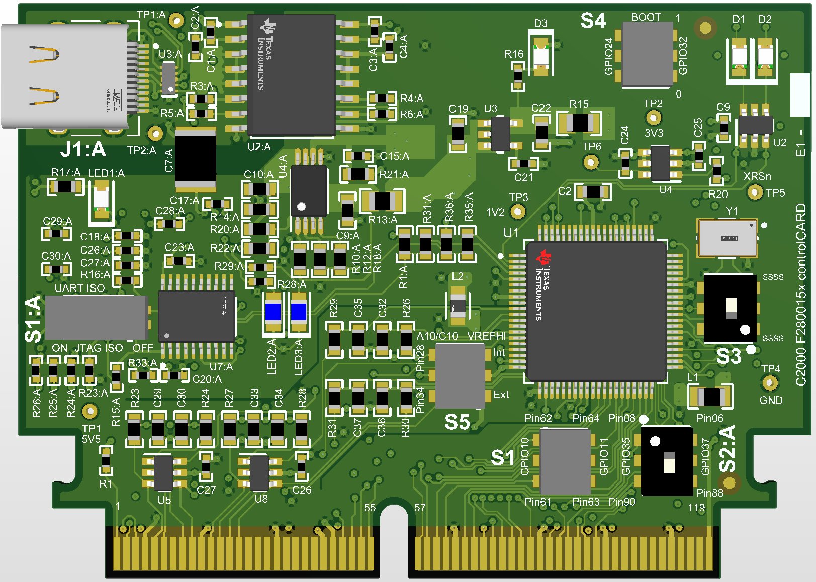
 Figure 1-1 F2800157 controlCARD
Each controlCARD comes with a Hardware Developer’s Kit, which is a full set of files necessary to evaluate and develop with a C2000 device. These files include:
- Schematics – Designed in Altium
- Bill of Materials (BOM)
- Layout PCB files - Designed in Altium
- Gerber files
The Hardware Developer's Kit for the controlCARD can be found in the C2000Ware at the following location:
-
<install
directory>\c2000\C2000Ware_x_xx_xx_xx\boards\controlCARDs\TMDSCNCD2800157\Rx_x
Note: This kit is designed to explore the
functionality of the F280015x microcontroller. The controlCARD can be treated as a
good reference design and is not intended to be a complete customer design. Full
compliance to safety, EMI/EMC, and other regulations are left to the designer of the
customer’s system.