SWRA577A October 2017 – November 2020 AWR1243 , AWR1443 , AWR1642 , AWR1843 , AWR1843AOP , AWR2243 , AWR6843 , IWR1443 , IWR1642 , IWR1843 , IWR6443 , IWR6843 , IWR6843AOP , LP87524B-Q1 , LP87524J-Q1
3 Reference Solution
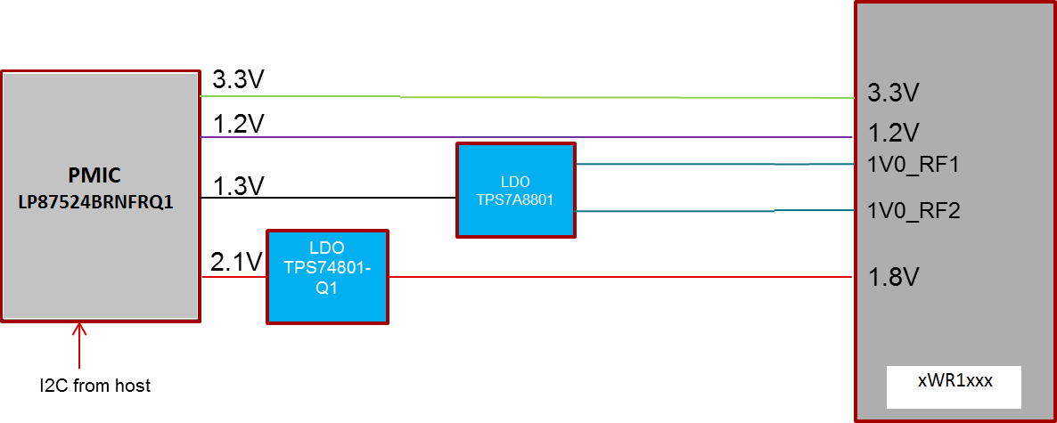
TI recommends the reference solution with the PMIC and the LDOs as shown in Figure 3-1, which is also incorporated in the XWR1xxx EVMs. The reference solution meets these specifications. The XWR1xx device would expect 1.0 V to be fed on the H5, G5, J5, D2 and C2 pins. The PMIC needs to be reconfigured for the Buck outputs shown in Figure 3-1 using the Inter-Integrated Circuit (I2C) interface from the host. Initially during the power up, the buck outputs would be 3.3 V, 1.2 V, 1.3 V and 2.1 V. Using I2C interface, the buck outputs needs to be reconfigured as shown in Figure 3-1 before the nRESET of XWR1xx is released.
 Figure 3-1 Power Management Scheme With LDOs
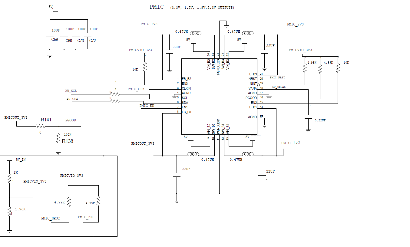
The above reference solution consists of the LP87524BRNFRQ1 PMIC with the switching frequency localized at 4 MHz, so that the fundamental and the harmonics could easily be filtered out during RADAR data post processing. The reference schematic is shown in Figure 3-2.
 Figure 3-2 Reference Schematic