TIDUEO1B April   2021  – June 2021


  1.   Description
  2.   Resources
  3.   Features
  4.   Applications
  5.   5
  6. 1General Texas Instruments High Voltage Evaluation (TI HV EVM) User Safety Guidelines
  7. 2System Description
    1. 2.1 Key System Specifications
  8. 3System Overview
    1. 3.1 Block Diagram
    2. 3.2 Design Considerations
      1. 3.2.1 Basic Operation
      2. 3.2.2 PCMC PSFB using C2000
    3. 3.3 System Design Theory
      1. 3.3.1 Peak Current Mode Control (PCMC) Implementation
      2. 3.3.2 Zero Voltage Switching (ZVS) or Low Voltage Switching (LVS)
      3. 3.3.3 Synchronous Rectification
      4. 3.3.4 Slope Compensation
    4. 3.4 Highlighted Products
      1. 3.4.1 C2000™ MCU F28004x
  9. 4Hardware, Software, Testing Requirements, and Test Results
    1. 4.1 Required Hardware and Software
      1. 4.1.1 Hardware
      2. 4.1.2 Software
        1. 4.1.2.1 Software Control Flow
        2. 4.1.2.2 Incremental Builds
        3. 4.1.2.3 Procedure for running the incremental builds - PCMC
          1. 4.1.2.3.1 Build 1: Peak Current Loop Check with Open Voltage Loop
            1. 4.1.2.3.1.1 Objective
            2. 4.1.2.3.1.2 Overview
            3. 4.1.2.3.1.3 Procedure
              1. 4.1.2.3.1.3.1 Start CCS and Open a Project
              2. 4.1.2.3.1.3.2 Build and Load the Project
              3. 4.1.2.3.1.3.3 Debug Environment Windows
              4. 4.1.2.3.1.3.4 Using Real-Time Emulation
              5. 4.1.2.3.1.3.5 Run the Code
          2. 4.1.2.3.2 Build 2: Closed current and voltage loop (Full PSFB)
            1. 4.1.2.3.2.1 Objective
            2. 4.1.2.3.2.2 Overview
            3. 4.1.2.3.2.3 Procedure
              1. 4.1.2.3.2.3.1 Build and Load Project
              2. 4.1.2.3.2.3.2 Debug Environment Windows
              3. 4.1.2.3.2.3.3 Run the Code
      3. 4.1.3 Test results
  10. 5Design and Documentation Support
    1. 5.1 Design Files
      1. 5.1.1 Schematics
      2. 5.1.2 BOM
    2. 5.2 Software
    3. 5.3 Documentation Support
  11. 6Terminology
  12. 7About the Author
  13. 8Revision History
Overview

Figure 4-9 shows the software blocks used in this build. A two pole two zero controller is used for the voltage loop. As shown in Figure 4-9, the voltage loop block is executed at 100 KHz. The DCL_runClamp_C1 function is used to avoid controller wind-up condition. The DCL_runDF22_C2 computes the immediate part of the pre-computed DF22 controller. If this value is larger than the max or less than min threshold, a flag will be set with DCL_runClamp_C1 function. This stops the further controller saturation. Once the flag is off, DCL_runDF22_C3 will compute the partial result of the pre-computed DF22 controller. More information on how the DCL function works could be found inside DCL user's guide in C2000ware.
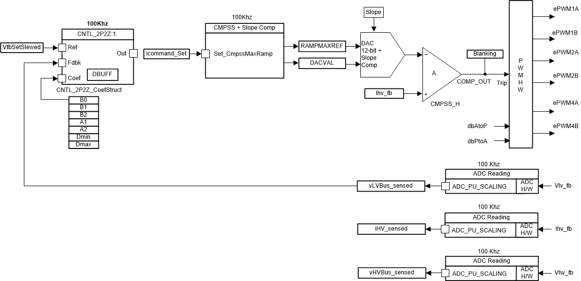
GUID-20201007-CA0I-B2SV-BV9S-37ZNJVLQZ9F9-low.gif Figure 4-9 Build 2 Software Block