SLAA494B May 2011 – September 2023 MSP430AFE221 , MSP430AFE222 , MSP430AFE223 , MSP430AFE231 , MSP430AFE232 , MSP430AFE233 , MSP430AFE251 , MSP430AFE252 , MSP430AFE253
- 1
- Implementation of a Single-Phase Electronic Watt-Hour Meter Using the MSP430AFE2xx
- 1 Trademarks
- 2 Introduction
- 3 Block Diagram
- 4 Hardware Implementation
- 5 Software Implementation
- 6 Energy Meter Demo
- 7 Results
- 8 Important Notes
- 9 Schematics
- 10References
- 11Revision History
3 Block Diagram
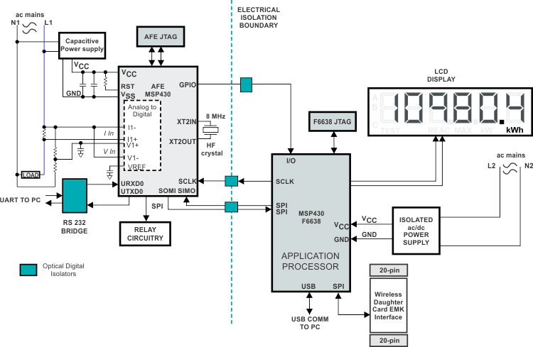
Figure 3-1 shows the system block diagram of the EVM. The EVM is divided into the metrology portion that has the MSP430AFE and the application portion that has the MSP430F6638. The MSP430AFE is a slave metrology processor and the MSP430F6638 is the host/application processor. The two MSP430 devices communicate through digital isolators via serial peripheral interface (SPI) or universal asynchronous receiver/transmitter (UART).
 Figure 3-1 Energy
Meter EVM System Block Diagram
Figure 3-1 Energy
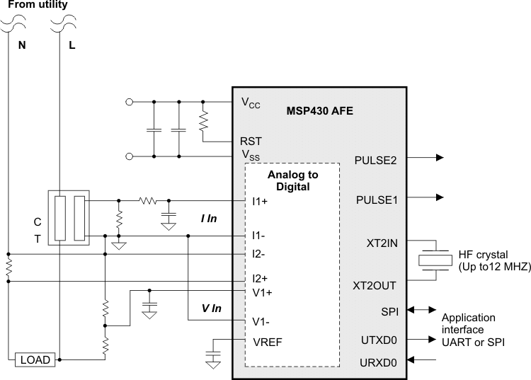
Meter EVM System Block DiagramFigure 3-2 shows the high-level interface for a single-phase energy-meter application. A single-phase two-wire star connection to the mains is shown with tamper detection. Current sensors are connected to each of the current channels, and a voltage divider is used for corresponding voltages. The current transformer (CT) has an associated burden resistor that must be connected at all times to protect the measuring device. The choice of the CT and the burden resistor is based on the manufacturer and current range required for energy measurements. The choice of the shunt resistor value is determined by the current range, gain settings of the SD24 on the AFE, and the tolerance of the power dissipation. The choice of voltage divider resistors for the voltage channel is selected to ensure the mains voltage is divided down to adhere to the normal input ranges that are valid for the MSP430 SD24. For these details, see the MSP430x2xx Family User's Guide and the device-specific data sheet.
 Figure 3-2 One-Phase
Two-Wire Star Connection Using MSP430AFE2x3