SLVUCO1A May 2023 – April 2024 DRV8213 , DRV8214 , DRV8234
PRODUCTION DATA
3.3 Connecting EVM to GUI
Now that the EVM hardware setup and GUI installation is complete, the EVM can now be connected to the GUI. The following steps outline how to connect the EVM to GUI:
- With the EVM connected to the PC, open the GUI.
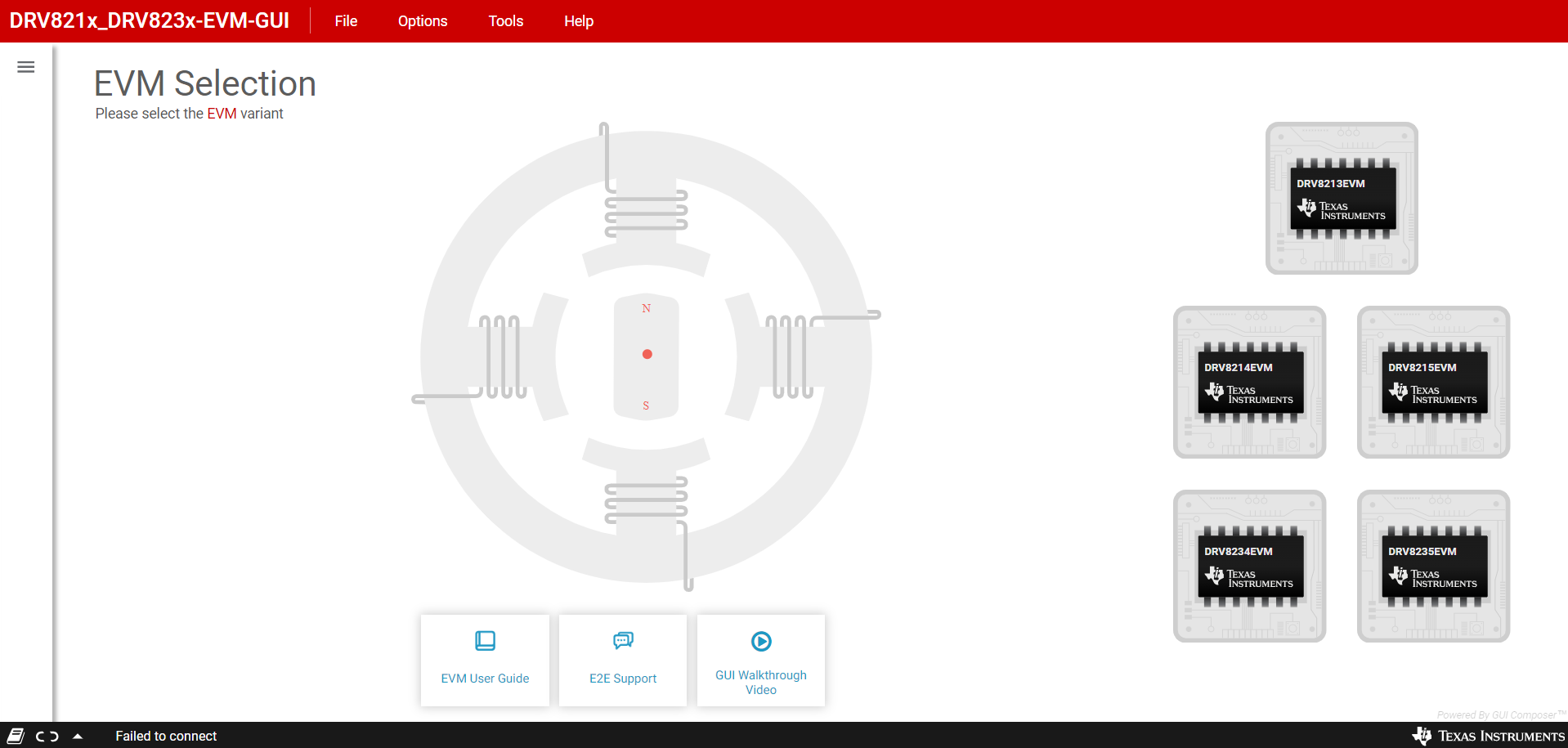
The home page is shown in Figure 4-2.
-
 Figure 3-2 GUI Landing
Page
-
- Program EVM with latest software by clicking on
File -> Program Device. (See Figure 4-3).
This needs to be done the first time the user sets up the EVM, as a software update can have been released since the EVM was initially programmed.
-
 Figure 3-3 Program
Device
-
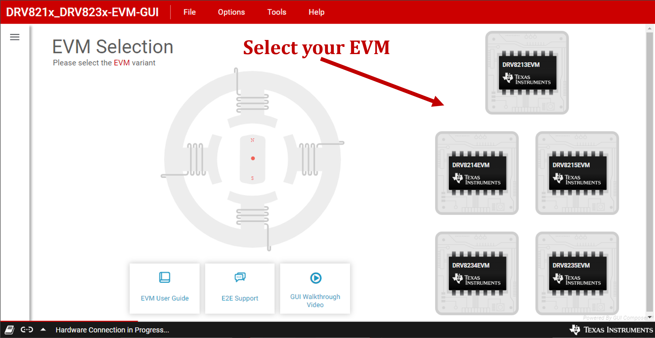
- Select the appropriate GUI variant from the five
options for the EVM (Figure 4-3).
-
 Figure 3-4 Select EVM
Variant
-
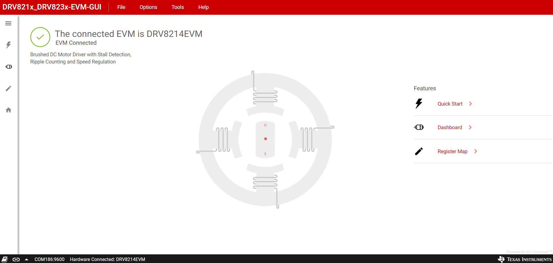
- The GUI attempts to connect with EVM. The GUI
displays the following once successfully connected. If there is no successful
connection, then double check hardware setup is correct following steps in Section 2.4.
-
 Figure 3-5 Successful GUI
connection
-
- Once successfully connected, click on Quick Start to open the QuickStart page, or Dashboard or Driver Control (DRV8213EVM) to open the main control page.
- The GUI setup is now complete. The following section provides an overview of the GUI and how to use the GUI to control EVM.