SNOA475F October 2016 – September 2020 LMV791
- Trademarks
- 1Introduction
-
2What Parameters Should Be Tested?
- 2.1 Open-Loop Gain (AOL) and Phase Margin
- 2.2 Slew Rate
- 2.3 Common-Mode Rejection Ratio (CMRR) and Power Supply Rejection Ratio (PSRR)
- 2.4 Open-Loop Output Impedance (Zo)
- 2.5 Voltage Noise (en)
- 2.6 Current Noise (in)
- 2.7 Input Offset Voltage (VOS), Input Bias Current (Ib), and Quiescent Current (IQ)
- 2.8 Output Voltage Versus Output Current (Claw Curve)
- 2.9 Overload Recovery Time (tOR)
- 2.10 Common-mode Input Capacitance (CCM) and Common-mode Differential Capacitance (CDIFF)
- 2.11 Overshoot and Transient Response
- 2.12 Common-Mode Voltage Range (CMVR)
- 3Conclusion
- Revision History
2.2 Slew Rate
Slew Rate is a measure of how fast an op amp's output can change. Slew rate is related to the ratio of the tail current and the compensation capacitance inside the op amp.
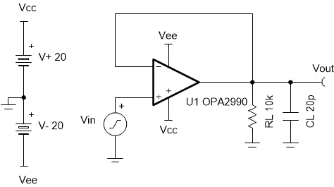
To measure slew rate, use a simple buffer circuit as shown in Figure 2-4. It is important to use the test circuit with the same load (RL and CL) indicated in the data sheet, in this example the OPA2990 data sheet specifies RL of 10 kΩ and a CL of 20 pF. This test circuit inputs a square wave and generates an output in which the slope of the rising edge and falling edge is the slew rate. The amplitude and time at 10 percent and 90 percent of the output's amplitude is used to calculate the slope, or slew rate. For more information on slew rate please refer to Texas Instruments Precision Labs video series on slew rate.
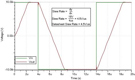
To assure this test circuit works properly, the square wave input should have an amplitude large enough so that the effects of slew rate limitation dominate. When running the simulation for slew rate, make sure the input signal rise and fall times are shorter the amplifier’s expected slew rate. This is to ensure that the test results are dominated by the amplifier’s slew rate. On the other hand, choose the input signal frequency accordingly with the op amp’s speed. An input signal that’s too fast will give you convergence problems. Figure 2-5 shows the simulated slew rate for OPA2990 and it corresponds with Figure 2-6 that shows the data sheet specification for slew rate. This circuit may be simulated by downloading the AN1516 Test Circuits in either TINA-TI™ or PSpice® for TI.
 Figure 2-4 Slew Rate Test
Circuit
 Figure 2-5 Simulated Slew Rate for
OPA2990
 Figure 2-6 Data Sheet Specification of
Slew Rate for OPA2990