SNOA475F October 2016 – September 2020 LMV791
- Trademarks
- 1Introduction
-
2What Parameters Should Be Tested?
- 2.1 Open-Loop Gain (AOL) and Phase Margin
- 2.2 Slew Rate
- 2.3 Common-Mode Rejection Ratio (CMRR) and Power Supply Rejection Ratio (PSRR)
- 2.4 Open-Loop Output Impedance (Zo)
- 2.5 Voltage Noise (en)
- 2.6 Current Noise (in)
- 2.7 Input Offset Voltage (VOS), Input Bias Current (Ib), and Quiescent Current (IQ)
- 2.8 Output Voltage Versus Output Current (Claw Curve)
- 2.9 Overload Recovery Time (tOR)
- 2.10 Common-mode Input Capacitance (CCM) and Common-mode Differential Capacitance (CDIFF)
- 2.11 Overshoot and Transient Response
- 2.12 Common-Mode Voltage Range (CMVR)
- 3Conclusion
- Revision History
2.4 Open-Loop Output Impedance (Zo)
Open-loop output impedance (Zo) is a specification that is often omitted from the data sheets but is very important when performing a stability analysis. Zo forms a RC circuit in combination with a capacitive load and plays a key role in where the pole is created in the AOL curve.
When modeled correctly, the Zo helps in getting a more accurate settling time behavior under various capacitive loads. Zo is also needed to calculate the proper component values when a compensation scheme is considered to assure the phase margin stays above 45 degrees. To learn more about Zo, please refer to Texas Instruments Precision Lab video series on Stability.
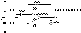
Figure 2-12 below shows the "Open Loop Output Impedance (Zo) Test Circuit." Zo is output impedance looking from the output of the op amp.
 Figure 2-12 Open Loop Output Impedance (Zo) Test Circuit
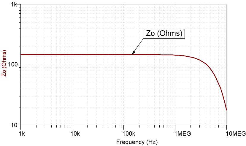
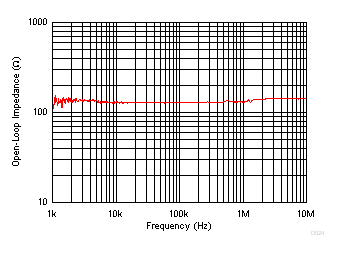
Simulated open-loop output impedance (Zo) is usually in decibels (dB). But, oftentimes data sheets represent this parameter in ohms (Ω) as shown in Figure 2-14. Figure 2-13 shows the simulation Zo for TLV6742 in ohms and Figure 2-14 shows the data sheet Zo plot for TLV6742. For a more complete simulation test analysis, please refer to the following EDN article, authored by Ian Williams. This circuit may be simulated by downloading the AN1516 Test Circuits in either TINA-TI™ or PSpice® for TI.
 Figure 2-13 Simulated Zo in
ohms (Ω) for TLV6742
 Figure 2-14 Data Sheet Graph of
Zo in ohms (Ω) for TLV6742