SPRUIR8B april 2020 – july 2023
- 1
- CLB Tool
- Trademarks
- 1Introduction
- 2Getting Started
- 3Using the CLB Tool
-
4Examples
- 4.1
Foundational Examples
- 4.1.1 CLB Empty Project
- 4.1.2 Example 3 – PWM Generation
- 4.1.3 Example 7 – State Machine
- 4.1.4 Example 13 – PUSH-PULL Interface
- 4.1.5 Example 14 – Multi-Tile
- 4.1.6 Example 15 – Tile to Tile Delay
- 4.1.7 Example 16 - Glue Logic
- 4.1.8 Exampe 18 - AOC
- 4.1.9 Example 19 - AOC Release Control
- 4.1.10 Example 20 - CLB XBARs
- 4.2
Getting Started Examples
- 4.2.1 Example 1 – Combinatorial Logic
- 4.2.2 Example 2 – GPIO Input Filter
- 4.2.3 Example 4 – PWM Protection
- 4.2.4 Example 5 – Event Window
- 4.2.5 Example 6 – Signal Generation and Check
- 4.2.6 Example 8 – External AND Gate
- 4.2.7 Example 9 – Timer
- 4.2.8 Example 10 – Timer With Two States
- 4.2.9 Example 11 – Interrupt Tag
- 4.2.10 Example 12 – Output Intersect
- 4.2.11 Example 17 – One-Shot PWM Generation
- 4.2.12 Example 21 - Clock Prescaler and NMI
- 4.2.13 Example 22 - Serializer
- 4.2.14 Example 23 - LFSR
- 4.2.15 Example 24 - Lock Output Mask
- 4.2.16 Example 25 - Input Pipeline Mode
- 4.2.17 Example 26 - Clocking Pipeline Mode
- 4.3 Expert Examples
- 4.1
Foundational Examples
- 5Enabling CLB Tool in Existing DriverLib Projects
- 6Frequently Asked Questions (FAQs)
- 7Revision History
3.3 Configuring a CLB Tile
To open the SysConfig tool, double-click on the “.syscfg” file you want to edit in the CCS Project Explorer window. A screen like that is shown in Figure 3-5.
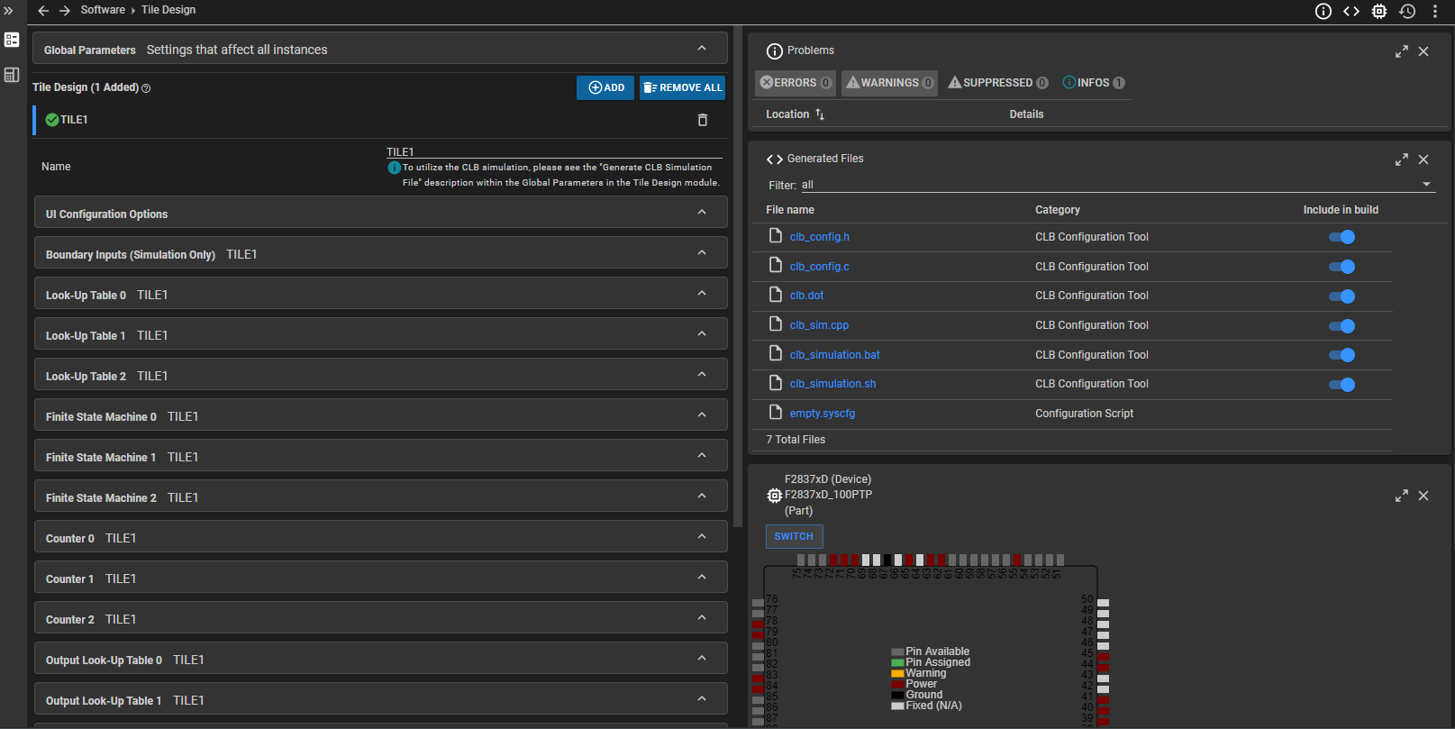 Figure 3-5 CLB Tool SysConfig
Screen
Figure 3-5 CLB Tool SysConfig
ScreenIf this screen does not open, be sure you have correctly completed the steps before this.
The configuration of CLB tiles are contained in the .syscfg file. You can change the name of the tile if desired. For the highlighted tile a list of sub-modules is shown in the pane to the right. The parameters of each sub-system can be inspected and edited by selecting the sub-module.
The “BOUNDARY” item is a special case. This group allows the user to select the tile inputs for simulation only. When the tool configuration is generated the CLB inputs always come from the CLB module within SysConfig, but for the purposes of simulation the user can specify a square wave signal source, together with a period and duty (both in clock cycles), synchronization, and input pipeline conditions as shown in Figure 3-6. Custom waveform generation for simulation purposes is also supported. For more information on the simulator, see Section 3.5. These options are only for simulation and do not affect the actual CLB configuration or its implementation on the device.
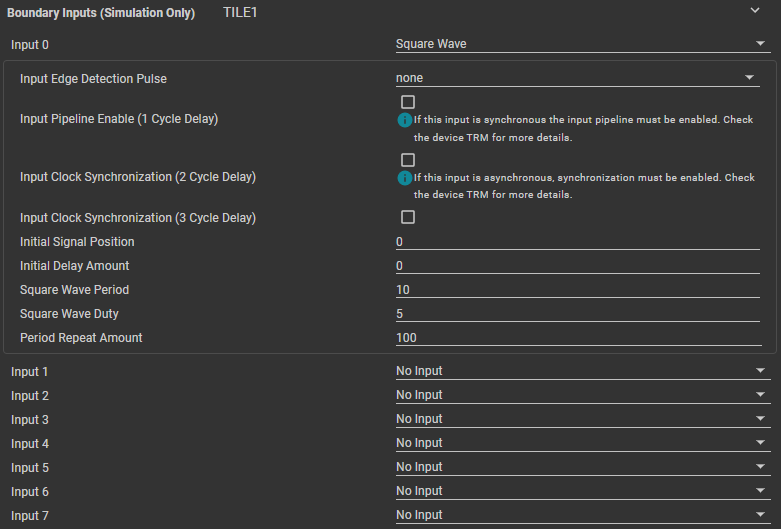 Figure 3-6 Boundary Input Options
The user configures and connects sub-modules in each tile using the check-boxes and drop-down options in the tool. All the sub-modules besides "BOUNDARY" also have a "User Description". This description is a multi-line text box where users can enter comments to help contextualize each part of the CLB.
 Figure 3-7 User Description Text
Box
Figure 3-7 User Description Text
BoxContext sensitive help appears when the mouse cursor is hovered over each item in the configuration tool. Figure 3-8 shows an example for the "Match Reference 1" field in the "Counter 0" sub-module.
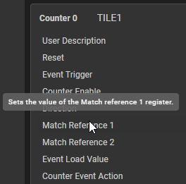 Figure 3-8 Counter Options
Logical equations for the LUTs and FSMs are configured by text entry using C format. Table 3-2 shows the symbols that are allowed in a Boolean equation.
| Logical Operation | Symbol |
|---|---|
| AND | & |
| OR | | |
| XOR | ^ |
| NOT | ! |
The use of parentheses is supported: for example, one could write: i1 | !(i2 & i3). The tool performs syntax checking on the equations as they are entered. Invalid equations are indicated by an error message below the entry line.
Some unlikely logical combinations generate a warning to the user. Figure 3-9 shows an example in which the user has attempted to use the i2 input in "LUT 0" in a Boolean equation. However, i2 is configured to be a constant which is unlikely to be what the user intended. The warning appears both below the equation and below the input selection.
 Figure 3-9 Equation Warning
For some fields, the tool performs range checking on numerical entries to ensure they lie within the allowable range. For example, an attempt to load a counter sub-module with a value greater than 232 will produce a warning because the counter is only 32 bits wide.
The tool automatically generates a number of files as the user enters configuration data. To view the generated files, click on the "< >” symbol in the upper right corner of the tool and select the filename to open it.
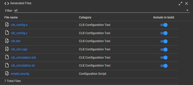 Figure 3-10 CLB Tool Generated
Files
Figure 3-10 CLB Tool Generated
FilesCLB register settings are contained in the header file “clb_config.h”, which can be opened by the user by clicking the filename. An example is shown in Figure 3-11. It is important to understand that this file is updated by the tool each time the user changes any CLB Tile Design settings. Therefore, manual changes to the contents of the generated files will be over-written by the tool. If the file is kept open while changing CLB settings, the the affected register data changing in the file can be viewed when the 'Unified Diff' option is selected.
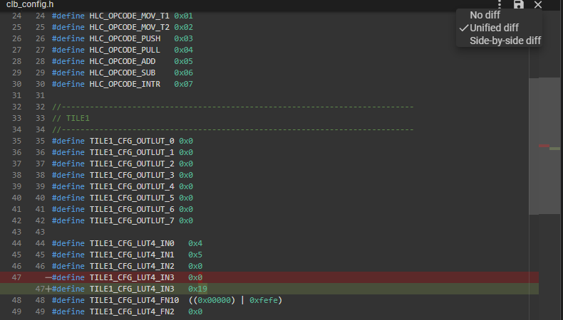 Figure 3-11 “clb.h” Header File
Example
Figure 3-11 “clb.h” Header File
ExampleThe file “clb.dot” allows the user to inspect a visual representation of the inter-connection of sub-modules. HTML and SVG versions of this block diagram are generated in the post-build steps that can be opened and viewed inside CCS.
 Figure 3-12 CLB Block Diagram
Fields for the HLC sub-module include those for configuring the events and initial values. Each of the four events can trigger execution of a short program consisting of up to eight instructions. For more information on the HLC, see the device-specific TRM.
HLC instructions can be entered in the "HLC Program" drop-down in "Other Dependencies". One blank line is always shown until all eight instructions have been used. In Figure 3-13, the user has selected one HLC trigger events and typed in a short program consisting of three instructions.
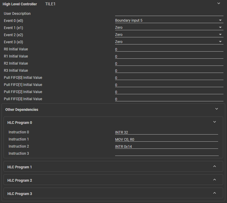 Figure 3-13 HLC Configuration
Example