SNVS032E February 2000 – January 2016 LM2651
PRODUCTION DATA.
- 1 Features
- 2 Applications
- 3 Description
- 4 Revision History
- 5 Pin Configuration and Functions
- 6 Specifications
- 7 Detailed Description
- 8 Application and Implementation
- 9 Power Supply Recommendations
- 10Layout
- 11Device and Documentation Support
- 12Mechanical, Packaging, and Orderable Information
Package Options
Mechanical Data (Package|Pins)
- PW|16
Thermal pad, mechanical data (Package|Pins)
Orderable Information
1 Features
- Ultrahigh Efficiency up to 97%
- High-Efficiency Over a 1.5-A to 1.5-mA Load Range
- 4-V to 14-V Input Voltage Range
- 1.8-V, 2.5-V, 3.3-V, or ADJ Output Voltage
- Internal MOSFET Switch With Low RDS(on) of
75 mΩ - 300-kHz Fixed Frequency Internal Oscillator
- 7-µA Shutdown Current
- Patented Current Sensing for Current Mode Control
- Input Undervoltage Lockout
- Adjustable Soft-Start
- Current Limit and Thermal Shutdown
- 16-Pin TSSOP Package
2 Applications
- Personal Digital Assistants (PDAs)
- Computer Peripherals
- Battery-Powered Devices
- Handheld Scanners
- High-Efficiency 5-V Conversion
3 Description
The LM2651 switching regulator provides high-efficiency power conversion over a 100:1 load range (1.5 A to 15 mA). This feature makes the LM2651 an ideal fit in battery-powered applications that demand long battery life in both run and standby modes.
Synchronous rectification is used to achieve up to 97% efficiency. At light loads, the LM2651 enters a low power hysteretic or sleep mode to maintain high efficiency. In many applications, the efficiency still exceeds 80% at 15-mA load. A shutdown pin is available to disable the LM2651 and reduce the supply current to less than 10 µA.
The LM2651 contains a patented current sensing circuitry for current mode control. This feature eliminates the external current sensing resistor required by other current-mode DC-DC converters.
The LM2651 has a 300-kHz fixed frequency internal oscillator. The high oscillator frequency allows the use of extremely small, low-profile components.
A programmable soft-start feature limits current surges from the input power supply at start-up and provides a simple means of sequencing multiple power supplies.
Other protection features include input undervoltage lockout, current limiting, and thermal shutdown.
Device Information(1)
| PART NUMBER | PACKAGE | BODY SIZE (NOM) |
|---|---|---|
| LM2651 | TSSOP (16) | 5.00 mm × 4.40 mm |
- For all available packages, see the orderable addendum at the end of the data sheet.
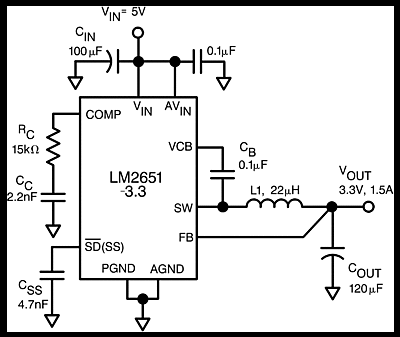
Typical Application
