SLVSD86B december 2015 – may 2023 TPS65265
PRODUCTION DATA
- 1
- 1 Features
- 2 Applications
- 3 Description
- 4 Revision History
- 5 Device Comparison Table
- 6 Pin Configuration and Functions
- 7 Specifications
-
8 Detailed Description
- 8.1 Overview
- 8.2 Functional Block Diagram
- 8.3
Feature Description
- 8.3.1 Adjusting the Output Voltage
- 8.3.2 Mix PGOOD, PG_DLY Functions
- 8.3.3 Enable and Adjusting UVLO
- 8.3.4 Soft-Start Time
- 8.3.5 Power-Up Sequencing
- 8.3.6 V7V Low Dropout Regulator and Bootstrap
- 8.3.7 Out of Phase Operation
- 8.3.8 Output Overvoltage Protection (OVP)
- 8.3.9 PSM
- 8.3.10 Slope Compensation
- 8.3.11 Overcurrent Protection
- 8.3.12 Adjustable Switching Frequency
- 8.3.13 Thermal Shutdown
- 8.4 Device Functional Modes
- 9 Application and Implementation
- 10Device and Documentation Support
- 11Mechanical, Packaging, and Orderable Information
Package Options
Mechanical Data (Package|Pins)
- RHB|32
Thermal pad, mechanical data (Package|Pins)
- RHB|32
Orderable Information
8.3.9 PSM
The TPS65265 can enter high-efficiency PSM operation at light load current when PSM pin connects to high or leave floating.
When a controller is enabled for PSM operation, the peak inductor current is sensed and compared with 180 mA current typically. Because the integrated current comparator catches the peak inductor current only, the average load current entering PSM varies with the applications and external output filters. In PSM, the sensed peak inductor current is clamped at 180 mA.
When a controller operates in PSM, the inductor current is not allowed to reverse. The reverse current comparator turns off the low-side MOSFET when the inductor current reaches zero, preventing it from reversing and going negative.
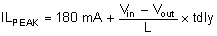
Due to the delay in the circuit and current comparator tdly (typical 50 ns at PVIN = 12 V), the real peak inductor current threshold to turn off high-side power MOSFET must shift higher depending on inductor inductance and input/output voltages. The threshold of peak inductor current to turn off high-side power MOSFET can be calculated by Equation 7.
After the charge accumulated on Vout capacitor is more than loading need, COMP pin voltage drops to low voltage driven by error amplifier. There is an internal comparator at COMP pin. If comp voltage is lower than 0.35 V, power stage stops switching to save power.
 Figure 8-8 PSM Current Comparator