JAJSMZ6 december 2021 UCC28781
PRODUCTION DATA
- 1
- 1 特長
- 2 アプリケーション
- 3 説明
- 4 Revision History
- 5 Pin Configuration and Functions
- 6 Specifications
-
7 Detailed Description
- 7.1 Overview
- 7.2 Functional Block Diagram
- 7.3
Detailed Pin Description
- 7.3.1 BUR Pin (Programmable Burst Mode)
- 7.3.2 FB Pin (Feedback Pin)
- 7.3.3 REF Pin (Internal 5-V Bias)
- 7.3.4 VDD Pin (Device Bias Supply)
- 7.3.5 P13 and SWS Pins
- 7.3.6 S13 Pin
- 7.3.7 IPC Pin (Intelligent Power Control Pin)
- 7.3.8 RUN Pin (Driver and Bias Source for Isolator)
- 7.3.9 PWMH and AGND Pins
- 7.3.10 PWML and PGND Pins
- 7.3.11 SET Pin
- 7.3.12 RTZ Pin (Sets Delay for Transition Time to Zero)
- 7.3.13 RDM Pin (Sets Synthesized Demagnetization Time for ZVS Tuning)
- 7.3.14 XCD Pin
- 7.3.15 CS, VS, and FLT Pins
- 7.4
Device Functional Modes
- 7.4.1 Adaptive ZVS Control with Auto-Tuning
- 7.4.2 Dead-Time Optimization
- 7.4.3 EMI Dither and Dither Fading Function
- 7.4.4 Control Law Across Entire Load Range
- 7.4.5 Adaptive Amplitude Modulation (AAM)
- 7.4.6 Adaptive Burst Mode (ABM)
- 7.4.7 Low Power Mode (LPM)
- 7.4.8 First Standby Power Mode (SBP1)
- 7.4.9 Second Standby Power Mode (SBP2)
- 7.4.10 Startup Sequence
- 7.4.11 Survival Mode of VDD (INT_STOP)
- 7.4.12
System Fault Protections
- 7.4.12.1 Brown-In and Brown-Out
- 7.4.12.2 Output Over-Voltage Protection (OVP)
- 7.4.12.3 入力過電圧保護 (IOVP)
- 7.4.12.4 FLT ピンの過熱保護 (OTP)
- 7.4.12.5 CS ピンの過熱保護 (OTP)
- 7.4.12.6 プログラム可能な過電力保護 (OPP)
- 7.4.12.7 ピーク電力制限 (PPL)
- 7.4.12.8 出力短絡保護 (SCP)
- 7.4.12.9 過電流保護 (OCP)
- 7.4.12.10 External Shutdown
- 7.4.12.11 Internal Thermal Shutdown
- 7.4.13 Pin Open/Short Protections
-
8 Application and Implementation
- 8.1 Application Information
- 8.2
Typical Application Circuit
- 8.2.1 Design Requirements for a 60-W, 15-V ZVSF Bias Supply Application with a DC Input
- 8.2.2 Detailed Design Procedure
- 8.2.3 Application Curves
- 9 Power Supply Recommendations
- 10Layout
- 11Device and Documentation Support
- 12Mechanical, Packaging, and Orderable Information
7.4.12.4 FLT ピンの過熱保護 (OTP)
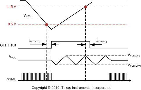
UCC28781 は、FLT ピンに接続された外付け NTC 抵抗 (RNTC) を使用して、コンバータのホットスポット付近でのサーマル・シャットダウン温度をプログラムします。NTC のシャットダウン・スレッショルド (VNTCTH) は 0.5V で、内部の 50μA 電流源が RNTC を流れると、10kΩ のサーミスタ・シャットダウン・スレッショルドになります。NTC の抵抗値が 50μs より長く 10kΩ を下回ると、OTP フォルト・イベントがトリガされます。50μs の遅延 (tFLT(NTC)) により、NTC 抵抗がコントローラから離れた場所にあり、ホット・スポットに近い場合、FLT ピンと AGND ピンとの間にフィルタ・コンデンサ (CFLT) を配置できます。RUN が High になるときに OTP フォルトが誤ってトリガされることを防ぐため、VFLT が tFLT(NTC) 内で VNTCTH を超えられるように CFLT を設計する必要があります。これに対して、NTC 抵抗がコントローラの近くにあり、検出配線への潜在的なノイズ結合パスが存在しない場合、CFLT は不要です。
回復のため、OTP フォルトの後で 0.5V のスレッショルドは 1.15V に増やされます。そのため、OTP フォルトをリセットするには、NTC 抵抗を 23kΩ より大きくする必要があります。このスレッショルドの変更により、安全な温度ヒステリシスが得られ、次の VO 再起動試行の前にホットスポットの温度が下がり、部品への熱ストレスが低減されます。FLT ピンを使用しない場合、このピンをフローティングのままにできますが、ライン OVP が誤ってトリガされるため、REF ピンには接続できません。
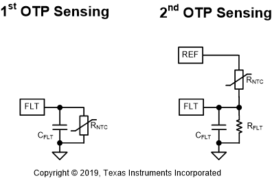
出力負荷が大きい条件での熱の問題は、OTP の設計上の主な考慮事項です。大きな負荷の動作モードである AAM を使用すると、コントローラを継続的に動作状態に維持できるため、50μs の遅延により VFLT で OTP をトリガできます。実用的な BUR ピンの設定に基づき、50%~60% の負荷は AAM で動作します。スタンバイ消費電力を節約するため、50μA の電流源は、ABM、LPM、SBP1、SBP2 などの軽負荷モードのバースト・オフ時間中はディセーブルされます。ただし、これらのモードで RUN 状態が 50μs よりも短く、電流源が WAIT 状態でディセーブルされているときは、フォルトを検出するのに十分な時間がないため、OTP はトリガできません。したがって、設計における特定の考慮事項の関係で、軽負荷モードでも OTP を有効にする必要がある場合、入力 OVP の 4.5V のスレッショルドを再利用することで、2 番目の OTP 構成が可能です。図 7-40 に示すように、上側の NTC 抵抗と下側の抵抗は、REF ピンから FLT ピンまでの分割抵抗を形成します。750μs の遅延はコントローラの待ち状態とは独立しているため、軽負荷モードでも OTP フォルトをトリガできます。
 図 7-40 FLT ピンに OTP を実装するための 2 つの接続
 図 7-41 FLT ピンと AGND ピンとの間の NTC の OTP タイミング図